
 HOT
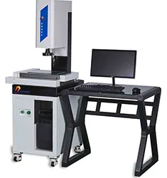
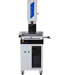
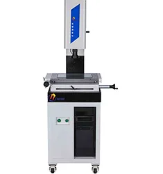
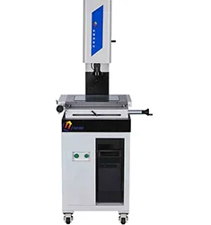
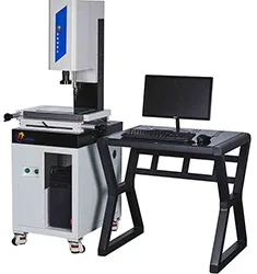
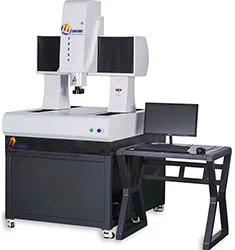
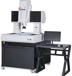
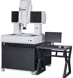
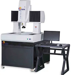
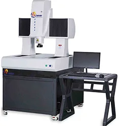
YR3020CNC-T CNC Vision Measuring Machine
CNC Vision Measuring Machine
- 测量工件尺寸300*200*180mm
- X/Y轴测量精度3+L/200um
HOTCNC Vision Measuring Machine
 HOT
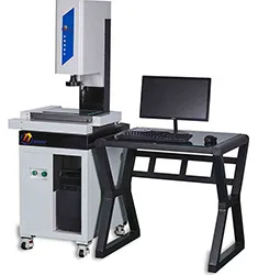
CNC Vision Measuring Machine
 HOT
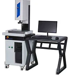
CNC Vision Measuring Machine
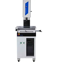
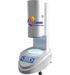
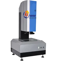
Automatic Vision Measuring Machine
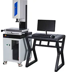
Automatic Vision Measuring Machine
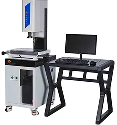
Automatic Vision Measuring Machine
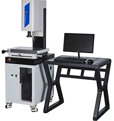
Automatic Vision Measuring Machine
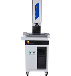
CNC Vision Measuring Machine
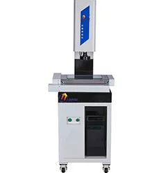
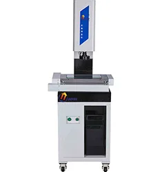
CNC Vision Measuring Machine
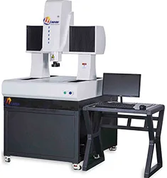
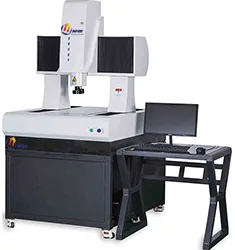
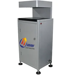
Vision Measuring Systems
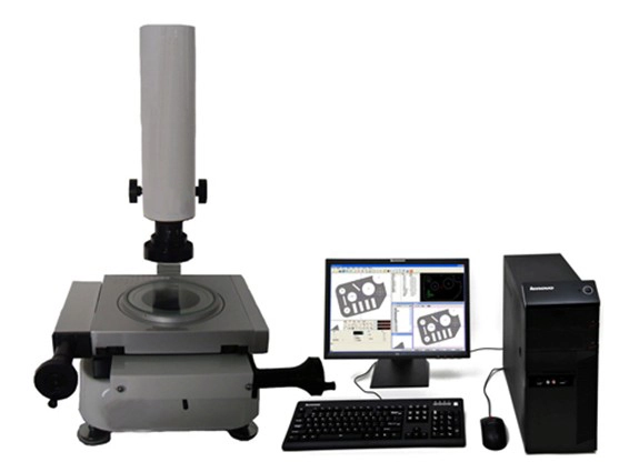
Vision measuring systems replace contact metrology with imaging: backlight turns part edges into a high-contrast silhouette, while surface and coaxial light reveal bores, blind holes and steps. After capture, software extracts sub-pixel edges, fits lines, circles and arcs by least squares, establishes a part coordinate system (3-2-1 or best-fit) and computes distances, angles, concentricity and position tolerance.
The stage is driven by servo motors and precision screws with linear encoder feedback (0.1–1 µm). CNC models automate the move–capture–measure sequence for batch inspection. Accuracy is typically stated as U = 2.0 + L/200 µm at 20 ± 2 °C.
Vision Measuring Systems
Vision Measuring Systems
1. Indication error: commonly E = (2.5 + L/150) µm (L in mm); at L = 200 mm, E ≈ 3.83 µm, verified with a glass ruler along the diagonals.
2. Pixel size: field width ÷ active pixels; an 8 mm field on 1280 px gives 6.25 µm/px, improved to 1/10 px by sub-pixel algorithms.
3. Circle fit: σ(diameter) ≈ σpoint/√n — use ≥16 points per least-squares circle.
4. True position: deviation Δ = 2√(Δx² + Δy²) versus tolerance zone φt; Δx=0.02, Δy=0.015 mm gives Δ = 0.05 mm.
5. Thermal correction: 100 mm of steel changes 1.2 µm per °C (α≈11.5×10⁻⁶/°C) — apply on the shop floor.
Vision Measuring Systems
| Standard | Title | Use |
|---|---|---|
| GB/T 24762-2009 | GPS — acceptance and reverification tests for imaging instruments | Acceptance, annual check |
| JJF 1318-2011 | Calibration specification for vision measuring instruments | Calibration |
| ISO 10360-7 | Acceptance tests for CMMs with imaging probing systems | Export projects |
| VDI/VDE 2617 | Accuracy of coordinate measuring machines | Accuracy rating |
| GB/T 1958-2017 | GPS — verification of geometrical tolerance | GD&T |
Vision Measuring Systems
1. Calculate travel first: maximum part envelope plus fixture plus approach margin, then add 20%. Sizing on the part alone is the classic mistake. YRVMS covers 150×100 to 1200×1500; larger parts need YRVMS5030 or gantry models.
2. Three accuracy numbers, not one: indication error (E), repeatability (R) and scale resolution. E = 2.5+L/200 µm is standard, 1.8+L/300 µm for precision work; a 0.001 mm display means nothing on its own.
3. Manual, motorised or CNC: manual (YRVMS1510F) for sampling, motorised (YRVMS2010E and up) for repetitive batches, CNC (YRVMS3020CNC and up) for programmed multi-feature and unattended runs.
4. Optics and lighting decide capability: 0.7–4.5× zoom with bi-telecentric optics for planar dimensions; laser or touch probe for height, blind holes and deep slots; coaxial light for polished metal, backlight for transparent parts.
5. Software, three questions: can it build a coordinate system from drawing datums rather than by eye, does it output FAI/PPAP sheets, and does it support SPC and Excel export.
6. In-line inspection is a different machine: use YR-MV for cycle-time-driven 100% inspection instead of a measuring machine.
| Series | Drive | Travel (mm) | Typical use |
|---|---|---|---|
| YRVMS1510F | Manual | 150×100 | Small-part sampling, teaching |
| YRVMS2010E / 2515F | Motorised / manual | 200×100 / 250×150 | Connectors, precision hardware |
| YRVMS3020CNC / 4030CNC | CNC | 300×200 / 400×300 | 3C FAI, batch programming |
| YRVMS5030 / 5030CNC | CNC | 500×300 | Mid-size structural parts |
| YRVMS120150 | Gantry CNC | 1200×1500 | Sheet and large contours |
| YR-MV1080 / 7070 | Dedicated vision | Custom | In-line 100% inspection |
| YR-QVS series | Flash measurement | Small field | One-click multi-dimension |
Acceptance advice: verify E with a glass scale after installation, check R by measuring the same part ten times, then compare against a part with known CMM results; the deviation should stay within E.
Vision Measuring Systems
Environment. 20 ± 2 °C, 40–60% RH, vibration-free; warm up 30 minutes; soak parts at least 2 hours (4 for large parts).
Calibration. Measure a glass scale or ceramic gauge block at near and far positions in X/Y/Z; perform ISO 10360-7 probing in seven directions with a length standard.
Measurement. Establish the coordinate system (plane–line–point or 3-2-1); take at least five points per feature (six for a circle, eight for a large circle); avoid chamfered edges; repeat each feature three times.
Verification. Check daily with a known artefact (50 mm block, certified circle); recalibrate when deviation exceeds one third of MPE.
Uncertainty. Dominated by temperature (11.5 × 10⁻⁶/°C × L), encoder error, edge algorithm and clamping repeatability; state U at k = 2.
Vision Measuring Systems
YRVMS2010E measures needle OD, ID, bevel angle and chamfer on 30 pieces in ten…
YR-MV1080 dedicated vision with rotary feeding inspects at 0.8 s per part with…
YRVMS2515F with bi-telecentric optics and programmable ring light measures all…
Five parts every two hours with a live CPK dashboard moved die maintenance fro…
YRVMS4030CNC with bi-telecentric optics measures 142 dimensions in one program…
YR4030CNC with 0.5 µm scales and motorised zoom measures 48 holes in one clamp…
엔지니어가 1영업일 내에 선정안, 검사 기준, 납기를 제안합니다.