 HOT
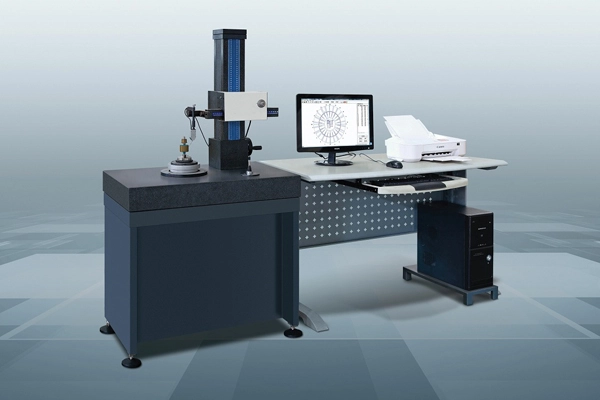
Y9025D Roundness Measuring Instrument
Roundness Measuring Instrument
- 主轴精度径向误差 / ±(0.025+5H/10000)μm
- 轴向误差±(0.025+6X/10000)μm
 MARSURF-XCR20 · 2026-11-17 · +86 21 5748 2007
Surface Roughness Tester
By submitting you agree to our privacy policy.
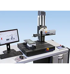
MARSURF XCR 20 粗糙度和轮廓测量站
在测量站使用 MarSurf XCR 20 测量粗糙度和轮廓
这个综合的测量站可在一台测量站上同时执行表面粗糙度和
轮廓测量。
根据测量任务,可使用 GD 25 驱动装置进行表面粗糙度测量,或使用 PCV 驱动装置进行轮廓测量。
两个测量系统通过组合支架固定到测量立柱。
节省空间型设计:两个驱动装置可使用相应的组装支架安装到 MarSurf ST 500 或 ST 750 测量立柱
一次测量即可完成粗糙度和轮廓评估
使用 MarSurf LD 130 / LD 260 测量系统对组件进行高精密度轮廓和粗糙度评估需要长行程和极高的分辨率
只需在软件平台内进行切换并更换驱动装置和测头等机械组件即可快速更换粗糙度和轮廓测量
MARSURF-XCR20 表面粗糙度轮廓仪技术参数:
接触速度(Z 方向)
0.1 至 1 mm/s
测杆长度
175 mm, 350 mm
测量速度(文本)
0.2 mm/s 至 4 mm/s
针尖半径
25
扫描长度末尾(X 方向)
200 mm
分辨率
Z 方向,相对探针针头:
0.38 μm(350 mm 测杆)/ 0.19 μm(175 mm 测杆)
Z 方向,相对测量系统:
0.04 μm
扫描长度开始(X 方向)
0.2 mm
取样角
在平滑表面上,取决于偏差:
后缘高至 88°,前缘高至 77°
定位速度(文本)
X 方向返回速度:0.2 至 8 mm/s
Z 方向:0.2 至 10 mm/s
导块偏差
< 1 μm(200 mm 以上)
测量原则
探针法
输入
R 测头,MFW 250
光学测头 Focodyn*、LS 1*、LS 10*
(*仅结合 PGK 或 GD 120 CNC 驱动装置)
测量范围 mm
(in Z) 50 mm
MFW 250: ±25 μm,±250 μm,(最高 ±750 μm);±1000 μin,±10,000 μin(最高 ±30,000 μm)
扫描长度(文本)
自动;0.56 mm;1.75 mm;5.6 mm;17.5 mm,56 mm,
(.022 / .070 / .224 / .700 / 2.240 英寸),
测量至挡块,可变
采样长度数量符合 ISO/JIS
1 至 50(默认:5)
测量力 (N)
1 mN 至 120 mN 左右
(可在 MarSurf XC 20 中设置)
MARSURF-XCR20 Surface Roughness Tester supplied by CHWES. 15 key specifications available on request.
| 测杆长度 | 175 mm, 350 mm |
|---|---|
| 测量速度(文本) | 0.2 mm/s 至 4 mm/s |
| 针尖半径 | 25 |
| 扫描长度末尾(X 方向) | 200 mm |
| 分辨率 | Z 方向,相对探针针头: 0.38 μm(350 mm 测杆)/ 0.19 μm(175 mm 测杆) Z 方向,相对测量系统: 0.04 μm |
| 扫描长度开始(X 方向) | 0.2 mm |
| 取样角 | 在平滑表面上,取决于偏差: 后缘高至 88°,前缘高至 77° |
| 定位速度(文本) | X 方向返回速度:0.2 至 8 mm/s Z 方向:0.2 至 10 mm/s |
| 导块偏差 | < 1 μm(200 mm 以上) |
| 测量原则 | 探针法 |
| 输入 | R 测头,MFW 250 光学测头 Focodyn*、LS 1*、LS 10* (*仅结合 PGK 或 GD 120 CNC 驱动装置) |
| 测量范围 mm | (in Z) 50 mm MFW 250: ±25 μm,±250 μm,(最高 ±750 μm);±1000 μin,±10,000 μin(最高 ±30,000 μm) |
| 扫描长度(文本) | 自动;0.56 mm;1.75 mm;5.6 mm;17.5 mm,56 mm, (.022 / .070 / .224 / .700 / 2.240 英寸), 测量至挡块,可变 |
| 采样长度数量符合 ISO/JIS | 1 至 50(默认:5) |
| 测量力 (N) | 1 mN 至 120 mN 左右 (可在 MarSurf XC 20 中设置) |
* Generated by rule engine over the product database; for pre-selection only.
A stylus instrument drags a diamond tip (2 or 5 µm radius) across the surface under constant force. The tip follows micro-relief, an inductive transducer converts displacement into a signal, and after amplification and filtering the profile is obtained. Per GB/T 10610 a Gaussian filter (or phase-corrected 2RC) with cut-off λc separates roughness from waviness; Ra, Rz, Rq, Rt and RSm are then computed over the sampling length.
Profile instruments share the same precision guide to capture roughness and macro profile, evaluating straightness, arc radius, angle, groove depth and pitch. Long-travel models (160–300 mm X, ±5 mm Z) suit shafts, rolls and mould surfaces.
1. Ra: arithmetic mean deviation, Ra = (1/n)Σ|zi| for sampled points; samples of 2, 4, 3, 5, 1 µm give Ra = 3 µm.
2. Rz: mean of the five highest peaks and five deepest valleys per sampling length (maximum peak-to-valley under GB/T 3505).
3. Rmr: material ratio curve at height c, describing the bearing capability of mating faces.
4. Filtering: Gaussian λc = 0.8/2.5/8 mm separates roughness from waviness; λs suppresses noise.
5. Roundness: least-squares centre, minimum-zone, minimum circumscribed or maximum inscribed; spindle error should be under 1/5 of the tolerance.
| Standard | Title | Use |
|---|---|---|
| GB/T 1031-2009 | Surface roughness — parameters and values | Parameter limits |
| GB/T 3505-2009 | Surface texture — profile terms | Terminology |
| GB/T 10610-2009 | Rules and procedures for assessment | Filtering, evaluation |
| ISO 4287 | Profile method — terms | Export projects |
| ISO 4288 | Rules and procedures | Sampling length |
1. Separate three quantities: roughness (Ra/Rz/Rmr, micrometre-scale microtexture), waviness (W, 0.1–10 µm mid-spatial), and form error (roundness, cylindricity, macro geometry). They need different instruments or filters.
2. Profilometers and roundness testers are not interchangeable: profilometers measure Ra/Rz and profile along a line (XZ, CX series); roundness testers measure roundness, cylindricity and coaxiality of bodies of revolution (Y90 series). A cylinder bore needing both requires two machines or a combined type.
3. Sensor range sets capability: ±50 µm suffices for Ra alone; deep grooves, steps and large arcs need ±500 µm or more; mirror surfaces below Ra 0.01 µm need low-noise sensors and isolation.
4. Travel and load: XZ-150 for small parts, XZ-230/XZ-150G for mid-size bores and shafts, Y901200 or custom stages above one metre.
5. Software must support the standards: full Ra/Rz/Rq/Rsk/Rku/Rmr per GB/T 1031 and ISO 4287; roundness per GB/T 7234 with minimum-zone, least-squares, minimum-circumscribed and maximum-inscribed evaluation.
6. On-site use: workshops need vibration and dust control; portable units (DY-300) suit large parts at lower accuracy.
| Model | Type | Capability | Typical parts |
|---|---|---|---|
| XZ-150 / XZ-150G | Roughness and profile | Ra/Rz + profile | Small precision parts |
| XZ-230 | Roughness and profile | Ra/Rz + long travel | Shafts, cylinder bores |
| CX-1(S) / CX-1(G) | Roughness | Ra/Rz/Rmr | Shop-floor sampling |
| CX-3/100 / CX-3/160 | Roughness and profile | Ra + profile + steps | Spools, sealing faces |
| 2207 / 2302A | Roundness | Roundness/cylindricity | Bearing rings, journals |
| Y9025B/C/D | Roundness | Roundness/coaxiality/waviness | Precision spindles, bores |
| Y9060 / Y901200 | Large roundness | Large-diameter roundness | Wind bearings, flanges |
| DY-300 | Portable | Ra/Rz | Large parts on site |
Why results disagree: wrong cut-off wavelength, insufficient evaluation length, mismatched stylus radius and an unlevelled part account for most disputes.
Preparation. Clean with ethanol to remove oil and chips; let the part stabilise to ambient (±2 °C); inspect the stylus at 20× for wear.
Settings. Choose λc to GB/T 1031 from expected Ra: 0.25 mm up to 0.1 µm, 0.8 mm for 0.1–2 µm, 2.5 mm for 2–10 µm, 8 mm above 10 µm; evaluation length 5 × λc.
Measurement. Stylus perpendicular to the lay, lower slowly, start when force is stable. Measure at least three positions per surface and average; on cylinders follow the generatrix.
Judgement. Compare with the drawing limit; no single reading should exceed 1.2 × the limit. Arbitrate with a profile instrument and a certified specimen.
Quality control. Daily check against Ra 0.4/1.6/6.3 specimens, recalibrate beyond 5% deviation, replace or verify the stylus every 12 months.
HOTRoundness Measuring Instrument
 HOT
Roundness Measuring Instrument
 HOT
Roundness Measuring Instrument
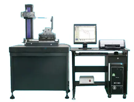
Surface Contour Measuring Instrument