
 HOT
Products
Photoelectric Autocollimators
0.1″ class, 10–50 m
Self-developed HXJL/HXM/HXDS photoelectric autocollimators with 0.1–1″ resolution and 10–50 m range, in single-axis, dual-axis and large-field versions, for straightness, flatness and precision angle metrology.
0.1″ class, 10–50 m
Photoelectric Autocollimators · 73 products
HOT HOT
 HOT
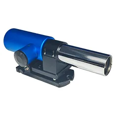
MC030-MAT200/38/1 Photoelectric Autocollimator (10 m1″)
Photoelectric Autocollimator · 10 m1″
- 型号MC030-MAT200/38/1
- 物镜焦距200mm
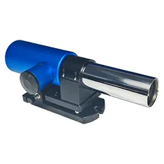
MC030-MAT200/38/0.5 Photoelectric Autocollimator (10 m0.5″)
Photoelectric Autocollimator · 10 m0.5″
- 型号MC030-MAT200/38/0.5
- 物镜焦距200mm
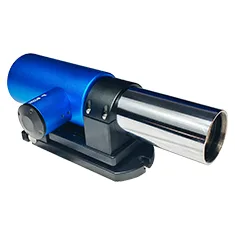
MC030-MAT200/48/1 Photoelectric Autocollimator (20 m1″)
Photoelectric Autocollimator · 20 m1″
- 型号MC030-MAT200/48/1
- 物镜焦距200mm
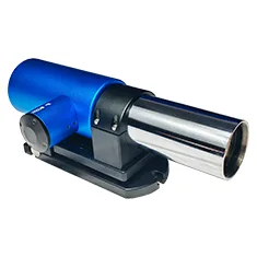
MC030-MAT200/48/0.5 Photoelectric Autocollimator (20 m0.5″)
Photoelectric Autocollimator · 20 m0.5″
- 型号MC030-MAT200/48/0.5
- 物镜焦距200mm
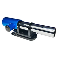
MC030-MAT300/48/1 Photoelectric Autocollimator (30 m1″)
Photoelectric Autocollimator · 30 m1″
- 型号MC030-MAT300/48/1
- 物镜焦距300mm
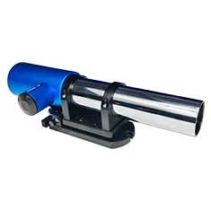
MC030-MAT300/48/0.5 Photoelectric Autocollimator (30 m0.5″)
Photoelectric Autocollimator · 30 m0.5″
- 型号MC030-MAT300/48/0.5
- 物镜焦距300mm
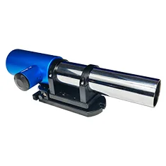
MC030-MAT300/48/0.3 Photoelectric Autocollimator (30 m0.3″)
Photoelectric Autocollimator · 30 m0.3″
- 型号MC030-MAT300/48/0.3
- 物镜焦距300mm
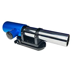
MC030-MAT300/48/0.2 Photoelectric Autocollimator (30 m0.2″)
Photoelectric Autocollimator · 30 m0.2″
- 型号MC030-MAT300/48/0.2
- 物镜焦距300mm
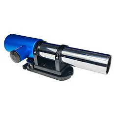
MC030-MAT300/48/0.1 Photoelectric Autocollimator (30 m0.1″)
Photoelectric Autocollimator · 30 m0.1″
- 型号MC030-MAT300/48/0.1
- 物镜焦距300mm
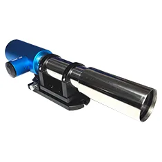
MC030-LD350/60/1 Photoelectric Autocollimator (40 m1″)
Photoelectric Autocollimator · 40 m1″
- 型号MC030-LD350/60/1
- 物镜焦距350mm
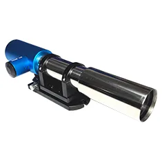
MC030-LD350/60/0.5 Photoelectric Autocollimator (40 m0.5″)
Photoelectric Autocollimator · 40 m0.5″
- 型号MC030-LD350/60/0.5
- 物镜焦距350mm
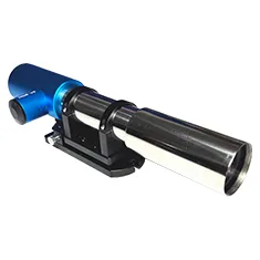
MC030-LD350/60/0.3 Photoelectric Autocollimator (40 m0.3″)
Photoelectric Autocollimator · 40 m0.3″
- 型号MC030-LD350/60/0.3
- 物镜焦距350mm
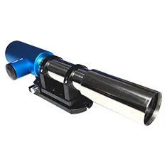
MC030-LD400/68/1 Photoelectric Autocollimator (50 m1″)
Photoelectric Autocollimator · 50 m1″
- 型号MC030-LD400/68/1
- 物镜焦距400mm
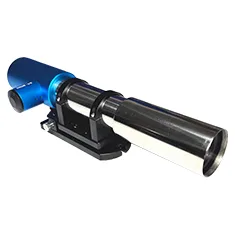
MC030-LD400/68/0.5 Photoelectric Autocollimator (50 m0.5″)
Photoelectric Autocollimator · 50 m0.5″
- 型号MC030-LD400/68/0.5
- 物镜焦距400mm
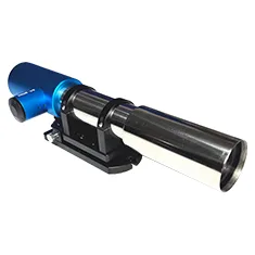
MC030-LD400/68/0.3 Photoelectric Autocollimator (50 m0.3″)
Photoelectric Autocollimator · 50 m0.3″
- 型号MC030-LD400/68/0.3
- 物镜焦距400mm
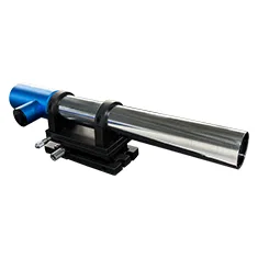
MC030-LD500/80/0.3 Photoelectric Autocollimator (80 m0.3″)
Photoelectric Autocollimator · 80 m0.3″
- 型号MC030-LD500/80/0.3
- 物镜焦距500mm
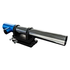
MC030-LD500/80/0.2 Photoelectric Autocollimator (80 m0.2″)
Photoelectric Autocollimator · 80 m0.2″
- 型号MC030-LD500/80/0.2
- 物镜焦距500mm
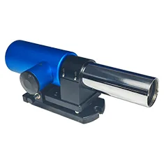
MC030-ZJUH2000/0.3 Photoelectric Autocollimator (10 m0.3″)
Photoelectric Autocollimator · 10 m0.3″
- 型号MC030-ZJUH2000/0.3
- 物镜焦距200mm
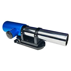
MC030-ZJUH3000/0.3 Photoelectric Autocollimator (30 m0.3″)
Photoelectric Autocollimator · 30 m0.3″
- 型号MC030-ZJUH3000/0.3
- 物镜焦距300mm
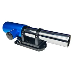
MC030-ZJUH3000/0.2 Photoelectric Autocollimator (30 m0.2″)
Photoelectric Autocollimator · 30 m0.2″
- 型号MC030-ZJUH3000/0.2
- 物镜焦距300mm
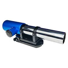
MC030-ZJUH3000/0.1 Photoelectric Autocollimator (30 m0.1″)
Photoelectric Autocollimator · 30 m0.1″
- 型号MC030-ZJUH3000/0.1
- 物镜焦距300mm
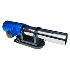
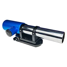
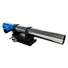
MC030-ZJUH5000/0.2 Photoelectric Autocollimator (50 m0.2″)
Photoelectric Autocollimator · 50 m0.2″
- 型号MC030-ZJUH5000/0.2
- 物镜焦距500mm
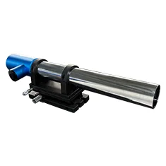
MC030-ZJUH5000/0.1 Photoelectric Autocollimator (50 m0.1″)
Photoelectric Autocollimator · 50 m0.1″
- 型号MC030-ZJUH5000/0.1
- 物镜焦距500mm
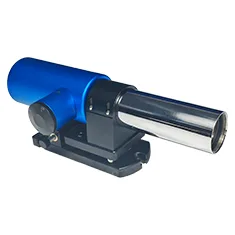
MC030-ZJHS200-200HZ Photoelectric Autocollimator
Photoelectric Autocollimator
- 型号MC030-ZJHS200-200HZ
- 物镜焦距200mm
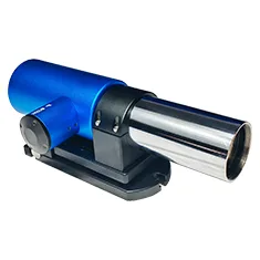
MC030-ZJPX200-2350HZ Photoelectric Autocollimator
Photoelectric Autocollimator
- 型号MC030-ZJPX200-2350HZ
- 物镜焦距200mm
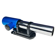
MC030-ZJPX300-2350HZ Photoelectric Autocollimator
Photoelectric Autocollimator
- 型号MC030-ZJPX300-2350HZ
- 物镜焦距300mm
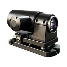
MC030-WF100-6000 Photoelectric Autocollimator
Photoelectric Autocollimator
- 型号MC030-WF100-6000
- 物镜焦距100mm
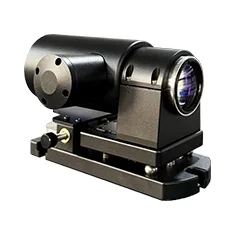
MC030-WF100-10800 Photoelectric Autocollimator
Photoelectric Autocollimator
- 型号MC030-WF100-10800
- 物镜焦距100mm
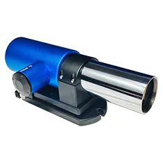
MC030-WF200-5700 Photoelectric Autocollimator
Photoelectric Autocollimator
- 型号MC030-WF200-5700
- 物镜焦距200mm
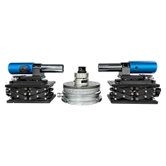
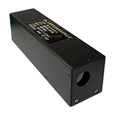
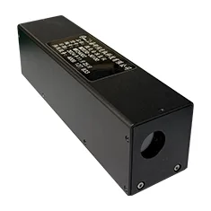
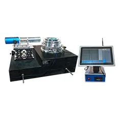
MC030-ZJQFCJY-1 Photoelectric Autocollimator
Photoelectric Autocollimator
- 型号MC030-ZJQFCJY-1
- 系统测量精度≤ ±1″
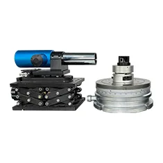
MC030-FDTCJY-0.3 Photoelectric Autocollimator
Photoelectric Autocollimator
- 型号MC030-FDTCJY-0.3
- 自准直仪物镜焦距300mm
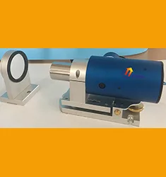
YRMAT1510 Photoelectric Autocollimator (10 m1″)
Photoelectric Autocollimator · 10 m1″
- 工作距离0-10m
- 物镜焦距150mm
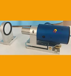
YRMAT1815 Photoelectric Autocollimator (15 m1″)
Photoelectric Autocollimator · 15 m1″
- 工作距离0-15m
- 物镜焦距180mm
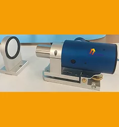
YRMAT2020 Photoelectric Autocollimator (20 m1″)
Photoelectric Autocollimator · 20 m1″
- 工作距离0-20m
- 物镜焦距200mm
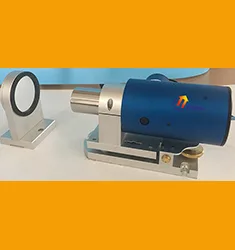
YRMAT3025 Photoelectric Autocollimator (25 m1″)
Photoelectric Autocollimator · 25 m1″
- 工作距离0-25m
- 物镜焦距300mm
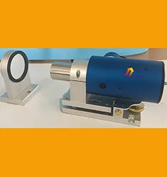
YRMAT3030 Photoelectric Autocollimator (30 m1″)
Photoelectric Autocollimator · 30 m1″
- 工作距离0-30m
- 物镜焦距300mm
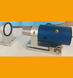
YRMAT3068M Photoelectric Autocollimator (40 m1″)
Photoelectric Autocollimator · 40 m1″
- 工作距离0-40m
- 物镜焦距360mm
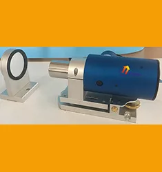
YRMAT1815B Photoelectric Autocollimator (15 m0.5″)
Photoelectric Autocollimator · 15 m0.5″
- 工作距离0-15m
- 物镜焦距180mm
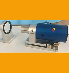
YRMAT2020B Photoelectric Autocollimator (20 m0.5″)
Photoelectric Autocollimator · 20 m0.5″
- 工作距离0-20m
- 物镜焦距200mm
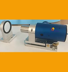
YRMAT3025B Photoelectric Autocollimator (25 m0.5″)
Photoelectric Autocollimator · 25 m0.5″
- 工作距离0-25m
- 物镜焦距300mm
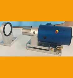
YRMAT3030B Photoelectric Autocollimator (30 m0.5″)
Photoelectric Autocollimator · 30 m0.5″
- 工作距离0-30m
- 物镜焦距300mm
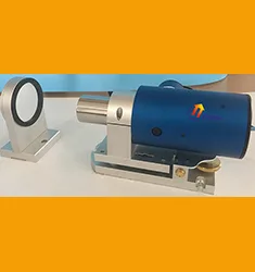
YRMAT3025C Photoelectric Autocollimator (25 m0.3″)
Photoelectric Autocollimator · 25 m0.3″
- 工作距离0-25m
- 物镜焦距300mm
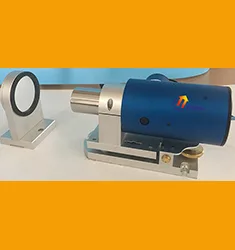
YRMAT3030C Photoelectric Autocollimator (30 m0.3″)
Photoelectric Autocollimator · 30 m0.3″
- 工作距离0-30m
- 物镜焦距300mm
S1401 Dual-axis Photoelectric Autocollimator (6-10 m)
Dual-axis Photoelectric Autocollimator · 6-10 m
- 工作距离0 -6米;(可定制10米)
- 物镜焦距400毫米
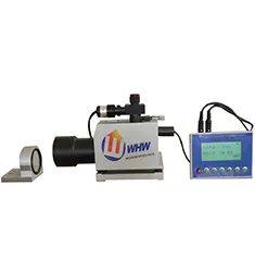
S1401-15 Dual-axis Photoelectric Autocollimator (15-20 m)
Dual-axis Photoelectric Autocollimator · 15-20 m
- 工作距离0-15米
- 物镜焦距550毫米
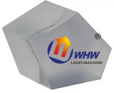
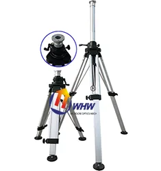
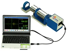
YR1000U-3050 Photoelectric Autocollimator (25/10 m)
Photoelectric Autocollimator · 25/10 m
- 物镜焦距300mm
- 物镜口径50mm (NA. = 90%)
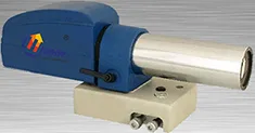
YR25PC02 Photoelectric Autocollimator (25 m,0.2arcsec)
Photoelectric Autocollimator · 25 m,0.2arcsec
- 物镜焦距300mm
- 物镜口径50mm(NA.=90%)
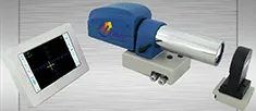
YR25TL02 Photoelectric Autocollimator (25 m,0.2arcsec)
Photoelectric Autocollimator · 25 m,0.2arcsec
- 物镜焦距300mm
- 物镜口径50mm(NA.=90%)
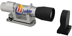
YR25D10 Photoelectric Autocollimator (25 m,1.0arcsec)
Photoelectric Autocollimator · 25 m,1.0arcsec
- 物镜焦距240mm
- 物镜口径60mm(NA.=90%)
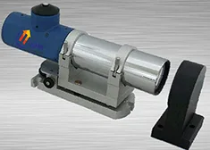
YR20TL05 Photoelectric Autocollimator (20 m,0.5arcsec)
Photoelectric Autocollimator · 20 m,0.5arcsec
- 物镜焦距200mm
- 物镜口径48mm(NA.=85%)
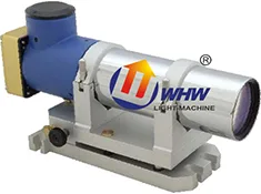
YR20W10 Photoelectric Autocollimator (20 m,1.0arcsec)
Photoelectric Autocollimator · 20 m,1.0arcsec
- 物镜焦距200mm
- 物镜口径48mm(NA.=85%)
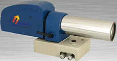
YR10PC01 Photoelectric Autocollimator (10 m,0.1arcsec)
Photoelectric Autocollimator · 10 m,0.1arcsec
- 物镜焦距300mm
- 物镜口径50mm(NA.=90%)
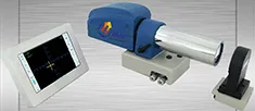
YR10TL01 Photoelectric Autocollimator (10 m,0.1arcsec)
Photoelectric Autocollimator · 10 m,0.1arcsec
- 物镜焦距300mm
- 物镜口径50mm(NA.=90%)
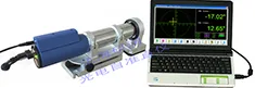
YR2038 Photoelectric Autocollimator (10 m,1arcsec)
Photoelectric Autocollimator · 10 m,1arcsec
- 测量距离10米
- 最大读数视场3000×2400 (角秒)
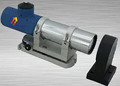
YR10TL03 Photoelectric Autocollimator (10 m,0.3arcsec)
Photoelectric Autocollimator · 10 m,0.3arcsec
- 物镜焦距300mm
- 物镜口径48mm(NA.=85%)
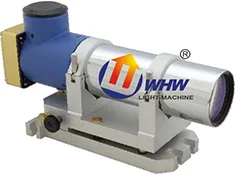
YR10W06 Photoelectric Autocollimator (10 m,0.6arcsec)
Photoelectric Autocollimator · 10 m,0.6arcsec
- 物镜焦距300mm
- 物镜口径48mm(NA.=85%)
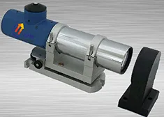
YR05TL02 Photoelectric Autocollimator (5 m,0.2arcsec)
Photoelectric Autocollimator · 5 m,0.2arcsec
- 物镜焦距1000mm
- 物镜口径100mm(NA.=90%)
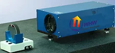
YR04TL001 Photoelectric Autocollimator (4 m,0.01arcsec)
Photoelectric Autocollimator · 4 m,0.01arcsec
- 物镜焦距1000mm
- 物镜口径100mm(NA.=90%)
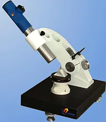
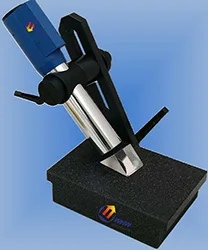
YR0515GMM Electronic Angle Comparator
Electronic Angle Comparator
- 型号YR15GMM、YR10GMM、YR05GMM
- 物镜焦距1;2;300mm
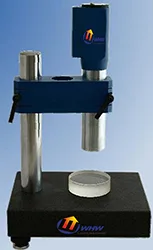
YROP10 Optical Parallelism Measuring Instrument
Optical Parallelism Measuring Instrument
- 物镜焦距200mm
- 物镜口径38mm(NA.=90%)
01
Working principle
Photoelectric Autocollimators
An autocollimator projects an illuminated cross-line as a parallel beam onto an external mirror. The mirror returns the beam, which re-images on the reticle or a CCD/CMOS sensor. If the mirror tilts by θ, the return image shifts by s = 2f·tanθ — the angle is doubled optically and magnified by the focal length.
Photoelectric readout (CCD/CMOS centroiding or PSD differential detection with software subdivision) reaches 0.1″ resolution. Dual-axis models read horizontal and vertical tilt simultaneously; large-field versions such as the HXDS15-4000 (4000×3000″) image a wide angular range for dynamic measurements.
Stepping a mirror bridge along a guideway converts per-step tilts θi into elevation differences hi = L·tanθi for straightness and flatness; with polygons or multi-tooth tables the same instrument calibrates circular indexing.
02
Process animation
Photoelectric Autocollimators
- Setup: mount the mirror on a bridge of span L at the start of the guideway.
- Zeroing: adjust the autocollimator until the cross image centres, record the initial reading.
- Step: advance the bridge by L each station, logging θi (both axes on dual-axis models).
- Evaluate: accumulate hi = L·tanθi and rate straightness or flatness by end-point or minimum-zone methods.
- Indexing: with a polygon, successive face readings give the index error; issue the report.
03
Calculation & formulas
Photoelectric Autocollimators
1. Angle-image relation: θ = s/(2f); with f = 500 mm and s = 5 µm, θ ≈ 1.03″ (1″ ≈ 4.85 µrad).
2. Resolution: 0.1″ corresponds to s ≈ 0.485 µm at f = 500 mm — pixels ≤5 µm plus 1/10 subdivision.
3. Elevation step: h = L·tanθ; a 100 mm bridge at 2″ gives h ≈ 0.97 µm.
4. End-point straightness: cumulative deviations Δi = Σhk − (i/n)Σh, error f = max(Δ) − min(Δ); the minimum-zone method rotates the datum per convex/concave/alternating criteria.
5. Indexing: per-face errors φj minus nominal; the closure Σφ = 0 checks the full circle.
04
Standards
Photoelectric Autocollimators
| Standard | Title | Scope |
|---|---|---|
| JJG 202-2007 | Verification regulation of autocollimators | Indication error and resolution |
| GB/T 11336-2004 | Detection of straightness error | Guideway and surface-plate straightness |
| GB/T 1958-2017 | GPS — detection and evaluation of geometrical deviations | Flatness, squareness and other form errors |
| ISO 230-1 | Machine tools — geometric accuracy tests | Machine acceptance |
| JJG 283-2007 | Multi-tooth indexing table verification | Circular indexing calibration |
Accredited labs must also hold 20±0.5 °C and vibration isolation, with instrument error within the 0.5″/1″ class.
05
Selection guide
Photoelectric Autocollimators
1. Resolution decides acceptance capability: 0.1″ (HXJL300-0.1, HXJL300U-0.1, HXJL300UH-0.1) for precision machines, rotary tables and laboratory standards; 0.2–0.3″ for general machine acceptance; 0.5–1″ (HXM series) for on-site alignment and long-range monitoring.
2. Distance decides aperture: 5–10 m with HXM2010/HXJL200; 20–30 m with HXM2020/HXM3030; 35–40 m with HXM3540; 50 m baseline with HXM4050M-1. Mirror aperture and light budget matter more as distance grows.
3. Single or dual axis: single-axis HXJL for one-direction straightness; dual-axis HXM for both directions and polygon indexing.
4. Dynamic work: HXDS15-4000 with a large field and high sampling rate for rotary-table oscillation, shaker tables and thermal drift.
5. Accessories: mirror bridges at 50/100/200 mm span, 12/24/36-face polygons, pentaprism for squareness, intermediate targets for long runs, thermal hoods for workshops.
6. Software and compliance: end-point, minimum-zone and least-squares evaluation with ISO 230-1 reports; labs also need the standard-artefact interface for verification.
| Model | Resolution | Distance | Typical use |
|---|---|---|---|
| HXJL300UH-0.1 | 0.1″ | 0–10 m | Precision tables, lab standards |
| HXJL300U-0.1 / HXJL300-0.1 | 0.1″ | 0–10 m | Precision guideways and plates |
| HXJL300-0.2 / -0.3 | 0.2–0.3″ | 0–10 m | General machine acceptance |
| HXM2010 / HXM2020 | 0.5–1″ | 10–20 m | Mid-size gantry, moulding machines |
| HXM3030 / HXM3540 | 0.5–1″ | 30–40 m | Large gantry, marine parts |
| HXM4050M-1 | 1″ | 50 m | Long guideways, cross-shop datums |
| HXDS15-4000 | Dynamic dual-axis | Large field | Table oscillation, vibration |
Common mistakes: using a 1″ unit to trend a 0.02 mm/m guideway; ignoring bridge sag under mirror weight; not controlling air currents and floor vibration, so readings never settle.
06
Test method
Photoelectric Autocollimators
Environment: 20±0.5 °C (±2 °C on the floor with compensation), shield air currents and sunlight; soak the instrument and bridge for 30 minutes on an isolated base.
Straightness procedure: ① clean the guideway and set the bridge span L; ② zero at the first station after 10 minutes of warm-up; ③ step by exactly L (within 0.5 mm), logging both axes; ④ evaluate by end-point and minimum-zone methods and report the larger; ⑤ record span, temperature and uncertainty (typically U ≈ 0.5″ + 2% of reading).
Intermediate checks: monthly 12-face polygon closure (Σ = 0, residual ≤0.3″); send standards out every two years.
Pitfalls: span errors feed straight into height differences; air currents jitter the centroid; thermal gradients bend long guideways optically — measure morning and afternoon and average.
07
Industry applications
Photoelectric Autocollimators
- Machine tools: gantry and boring-mill guideway straightness, column and spindle squareness, table flatness to ISO 230-1 and GB/T 11336; repeatability ≤1 µm over 24 m with the end-point method.
- Metrology institutes: surface-plate flatness, cross-checks with electronic levels, small-angle standard build-up; indication error within ±0.5″/±1″ per JJG 202-2007.
- Indexing and rotary tables: multi-tooth tables, optical and CNC rotary tables, RV reducer backlash; full-circle checks with 12/24/36-face polygons, indexing error ≤±1″.
- Semiconductor stages: micro-angle feedback and thermal drift monitoring on air-bearing and wafer stages, resolution ≤0.01″ at ≥10 Hz.
- Inertial navigation and optics: reference-mirror alignment and angle transfer for gyro platforms, theodolites and interferometers.
- Energy equipment: turbine bearing alignment, wind-turbine flange squareness, long hydro shaft lines.
- Rail and elevators: guide-rail straightness and twist, body datum flatness, often at 30–50 m working distance.
- Research and teaching: optical bench levelling and micro-angle measurement.
Industry cases
View all→Case Studies
On-site straightness and twist of 50 m guide rails
HXM4050M-1 measures straightness and twist over 50 m in 12 minutes per rail, r…
1 h → 12 minPer rail
≤0.05 mmRepeatability
Micro-angle drift monitoring of an air-bearing stage at 0.01″
HXJL300UH-0.1 sampled at 10 Hz for eight hours quantified pitch and yaw therma…
0.11″ → 0.03″Pitch drift
0.01″Resolution
Full-circle indexing check of a five-axis table with a 24-face polygon
HXM2020-0.5 with a 24-face polygon cuts a 15-position table calibration from s…
6 h → 70 minPer table
≤0.8″Repeatability
Dual-axis indexing calibration of a 360-tooth table
HXM2010-1 dual-axis autocollimator with a 24-face polygon measured a 360-tooth…
±0.08″Index error
2.5 hVerification time
24 m gantry guideway acceptance at 0.1″
HXJL300UH-0.1 with a 500 mm bridge stepped 48 stations over 24 m; minimum-zone…
8.2 μmStraightness
65 minTime
0.1 arcsec straightness acceptance of VMC Z axis
MC030-ZJUH3000/0.1 measures bidirectional straightness over 800 mm Z travel pe…
0.1″Resolution
40 minTime per machine
Price and lead time for this model
Our engineers reply within one business day with selection advice, acceptance criteria and lead time.