
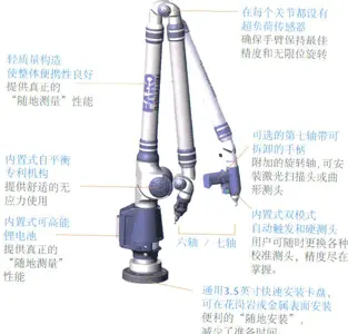
MC003-PLARM Portable platinum measuring arm
Full 3D dimensional and GD&T inspection
- Control便携式关节测量臂,6 轴/7 轴
- Accuracy接触式测头 + 可选激光扫描头
Portable arms and bridge CMMs
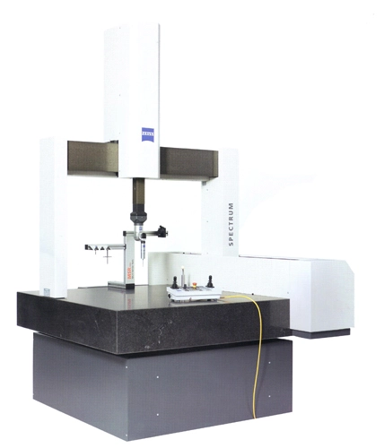
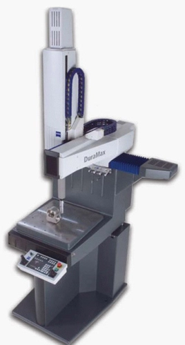
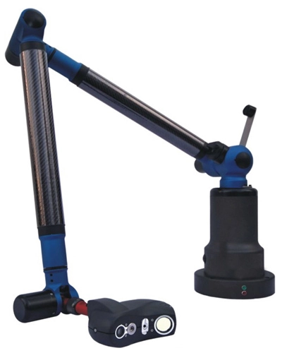
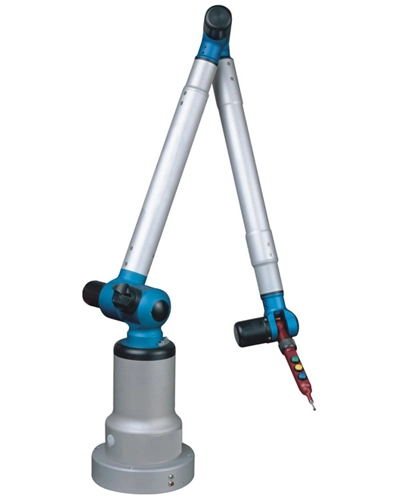
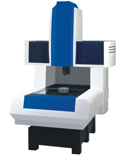
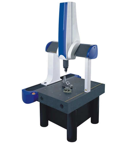
MC003 portable measuring arms (platinum, titanium, laser scanning) and bridge CMMs such as Spectrum, Atlas and DuraMax cover shop-floor large-part checks and laboratory GD&T evaluation.
Full 3D dimensional and GD&T inspection
Full 3D dimensional and GD&T inspection
Full 3D dimensional and GD&T inspection

Full 3D dimensional and GD&T inspection
Full 3D dimensional and GD&T inspection
Full 3D dimensional and GD&T inspection
Full 3D dimensional and GD&T inspection
Full 3D dimensional and GD&T inspection
Full 3D dimensional and GD&T inspection
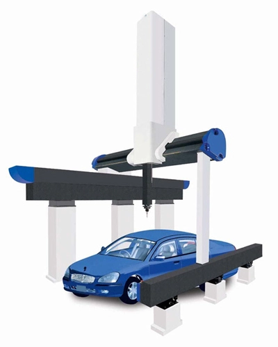
Full 3D dimensional and GD&T inspection
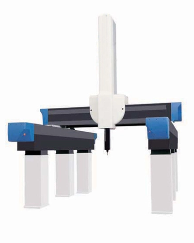
Full 3D dimensional and GD&T inspection
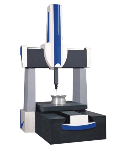
Full 3D dimensional and GD&T inspection
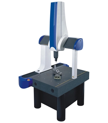
Full 3D dimensional and GD&T inspection
Full 3D dimensional and GD&T inspection
Coordinate Measuring Machines
A bridge CMM carries the probe along X/Y/Z on linear scales resolving 0.01–0.1 µm class. Touch-trigger probes lock coordinates on contact; scanning probes stream surface points; non-contact laser heads capture millions of points per second for free-form or soft parts.
A 21-term geometric error model (positioning, straightness, squareness, angularity) is compensated in software, with thermal sensors correcting at α = 11.5×10⁻⁶/°C for steel.
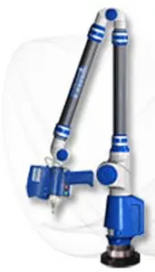
Portable arms (MC003) serialise six encoded joints, solving the tip position by the D-H model — on-site measurement of large parts; with a laser head they become reverse-engineering scanners.
Coordinate Measuring Machines
Coordinate Measuring Machines
1. Two-point distance: d = √(Δx²+Δy²+Δz²) with u(d) ≈ √2·uaxis.
2. Thermal: ΔL = L·α·ΔT; a 300 mm steel part 2 °C off nominal shifts 6.9 µm — correct or measure at 20 °C.
3. True position: Δ = 2√(Δx²+Δy²) versus φt; Δx=0.03, Δy=0.04 mm gives Δ=0.10 mm, failing φ0.08.
4. Uncertainty budget: uc = √(ucmm²+uprobe²+utemp²+ufixturing²); with 1.8, 0.6, 1.0 and 0.8 µm terms uc ≈ 2.3 µm (U ≈ 4.6 µm, k=2).
5. Roundness: least-squares roundness = max(ri)−min(ri); arbitration by minimum zone.
Coordinate Measuring Machines
| Standard | Title | Scope |
|---|---|---|
| ISO 10360-2 | CMM acceptance and re-verification, Part 2 | MPE_E0 testing |
| GB/T 16857.2 | GPS — CMM acceptance in China | National acceptance |
| ISO 1101 | GPS — geometrical tolerancing | GD&T evaluation |
| GB/T 1958 | GPS — detection of geometrical deviations | Form-error methods |
| ISO/TS 15530-3 | Uncertainty assessment for CMMs | Task-specific U budgets |
Job sheets must record temperature, probe configuration, point strategy and fixturing for reproducibility.
Coordinate Measuring Machines
1. Locate by accuracy and travel: set travel from the largest part plus 150–200 mm for fixturing, then pick accuracy from the tolerance. MPE_E 2.2+L/350 covers most automotive and general work, 1.8+L/300 precision moulds, below 1.2+L/300 aerospace and gauge work.
2. Structure follows the part: bridge machines (Atlas, Daisy) for small and mid-size batches; gantry (ML) for heavy parts; arms (MC003-SCANARM) for large parts on site; shop-floor machines (DuraMax, Spectrum) next to the line.
3. Probes define capability: touch-trigger for dimensions and GD&T, scanning for surfaces and point clouds, laser for fast reverse engineering. Budget probe and software together with the frame.
4. Software is the long-term cost: DMIS program exchange, native GD&T evaluation rather than custom scripting, PPAP/FAI output, offline programming.
5. Environment is a precondition: 20±2 °C, gradient ≤1 °C/h, vibration ≤VC-C. Buying accuracy without a controlled room wastes money.
6. Accept to ISO 10360: MPE_P with a standard sphere plus MPE_E, and ask for the 21-parameter error compensation report.
| Series | Structure | MPE_E | Typical use |
|---|---|---|---|
| Daisy | Bridge, economy | 2.5+L/300 | General hardware, teaching |
| Atlas / Atlas-B | Bridge | 2.2+L/350 | Automotive parts, housings |
| MGH high accuracy | Bridge, rigid | 1.2+L/300 | Precision moulds, gauges |
| ML series | Gantry | 3.0+L/300 | Large structures, castings |
| UG / Spectrum | Shop-floor | 3.5+L/300 | Near-line inspection |
| MC003-SCANARM | Arm with scanning | 0.03 mm (arm dependent) | Large parts on site, reverse engineering |
| MC003-GAGEPLUS | Dedicated gauge | Part specific | Fast batch go/no-go |
What drives the price: accuracy class, travel, probe and scanning package, software modules, temperature room and air supply. The same travel can differ two to three times, so never compare frame price alone.
Coordinate Measuring Machines
Environment: 20±1 °C, gradient ≤0.5 °C/h, 40–60% RH; soak parts ≥4 h (overnight for large ones).
Fixturing: 3- or 6-point support without clamping distortion; low-stress support paste for thin walls.
Datums: 3-2-1 from drawing features; otherwise CAD best-fit, logging RMS residuals.
Point strategy: 4–6 points on ≤10 mm holes, ≥6 points over the full plane, scan spacing ≤0.5 mm on free forms.
Checks: reference sphere or gauge block each shift; quarterly ISO 10360 interim checks archived.
Pitfalls: thermal soak shortcuts, over-long styli, excessive scan speed, mis-built datums.
Coordinate Measuring Machines
MGH with a scanning probe compares 120,000 cavity points in 35 minutes; the co…
MC003-SCANARM measures an 8 m boom on site in 90 minutes, replacing a two-day …
Atlas-B with a scanning probe measures 214 features in 22 minutes with positio…
The MC003-SCANARM verified flatness of a DN2400 flange gasket face and bevel a…
A Spectrum bridge CMM with hybrid probing finished 86 GD&T items in 12 minutes…
Atlas gantry CMM, accepted per ISO 10360-2, measures 320 gap and flush points …
Our engineers reply within one business day with selection advice, acceptance criteria and lead time.