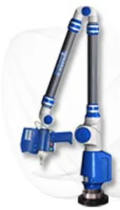
MC003-SCANARM 3D laser scanning measuring arm
Full 3D dimensional and GD&T inspection
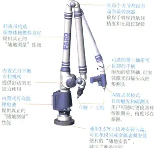
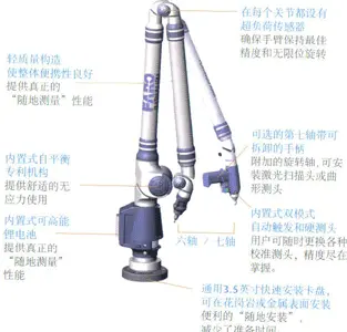
- Control便携式关节测量臂,6 轴/7 轴
- Accuracy接触式测头 + 可选激光扫描头
 MC003-PLARM · 2026-11-17 · +86 21 5748 2007
Full 3D dimensional and GD&T inspection
By submitting you agree to our privacy policy.
The MC003-PLARM solution covers portable arms to high-accuracy bridge CMMs, with touch probes or laser scanning.
The MC003-PLARM solution covers portable arms to high-accuracy bridge CMMs, with touch probes or laser scanning.
| Control | 便携式关节测量臂,6 轴/7 轴 |
|---|---|
| Accuracy | 接触式测头 + 可选激光扫描头 |
| Measuring range | 按型号规格,详见选型表 |
| Software | 专业测量与评价软件(尺寸/形位公差) |
| Profile parameters | 适用于箱体、叶片、模具、结构件全尺寸检测 |
* Generated by rule engine over the product database; for pre-selection only.
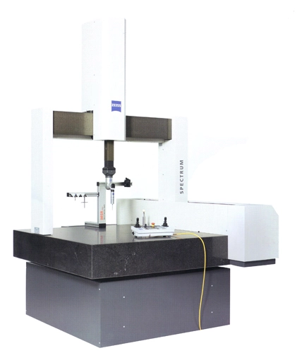
A bridge CMM carries the probe along X/Y/Z on linear scales resolving 0.01–0.1 µm class. Touch-trigger probes lock coordinates on contact; scanning probes stream surface points; non-contact laser heads capture millions of points per second for free-form or soft parts.
A 21-term geometric error model (positioning, straightness, squareness, angularity) is compensated in software, with thermal sensors correcting at α = 11.5×10⁻⁶/°C for steel.
Portable arms (MC003) serialise six encoded joints, solving the tip position by the D-H model — on-site measurement of large parts; with a laser head they become reverse-engineering scanners.
1. Two-point distance: d = √(Δx²+Δy²+Δz²) with u(d) ≈ √2·uaxis.
2. Thermal: ΔL = L·α·ΔT; a 300 mm steel part 2 °C off nominal shifts 6.9 µm — correct or measure at 20 °C.
3. True position: Δ = 2√(Δx²+Δy²) versus φt; Δx=0.03, Δy=0.04 mm gives Δ=0.10 mm, failing φ0.08.
4. Uncertainty budget: uc = √(ucmm²+uprobe²+utemp²+ufixturing²); with 1.8, 0.6, 1.0 and 0.8 µm terms uc ≈ 2.3 µm (U ≈ 4.6 µm, k=2).
5. Roundness: least-squares roundness = max(ri)−min(ri); arbitration by minimum zone.
| Standard | Title | Scope |
|---|---|---|
| ISO 10360-2 | CMM acceptance and re-verification, Part 2 | MPE_E0 testing |
| GB/T 16857.2 | GPS — CMM acceptance in China | National acceptance |
| ISO 1101 | GPS — geometrical tolerancing | GD&T evaluation |
| GB/T 1958 | GPS — detection of geometrical deviations | Form-error methods |
| ISO/TS 15530-3 | Uncertainty assessment for CMMs | Task-specific U budgets |
Job sheets must record temperature, probe configuration, point strategy and fixturing for reproducibility.
1. Locate by accuracy and travel: set travel from the largest part plus 150–200 mm for fixturing, then pick accuracy from the tolerance. MPE_E 2.2+L/350 covers most automotive and general work, 1.8+L/300 precision moulds, below 1.2+L/300 aerospace and gauge work.
2. Structure follows the part: bridge machines (Atlas, Daisy) for small and mid-size batches; gantry (ML) for heavy parts; arms (MC003-SCANARM) for large parts on site; shop-floor machines (DuraMax, Spectrum) next to the line.
3. Probes define capability: touch-trigger for dimensions and GD&T, scanning for surfaces and point clouds, laser for fast reverse engineering. Budget probe and software together with the frame.
4. Software is the long-term cost: DMIS program exchange, native GD&T evaluation rather than custom scripting, PPAP/FAI output, offline programming.
5. Environment is a precondition: 20±2 °C, gradient ≤1 °C/h, vibration ≤VC-C. Buying accuracy without a controlled room wastes money.
6. Accept to ISO 10360: MPE_P with a standard sphere plus MPE_E, and ask for the 21-parameter error compensation report.
| Series | Structure | MPE_E | Typical use |
|---|---|---|---|
| Daisy | Bridge, economy | 2.5+L/300 | General hardware, teaching |
| Atlas / Atlas-B | Bridge | 2.2+L/350 | Automotive parts, housings |
| MGH high accuracy | Bridge, rigid | 1.2+L/300 | Precision moulds, gauges |
| ML series | Gantry | 3.0+L/300 | Large structures, castings |
| UG / Spectrum | Shop-floor | 3.5+L/300 | Near-line inspection |
| MC003-SCANARM | Arm with scanning | 0.03 mm (arm dependent) | Large parts on site, reverse engineering |
| MC003-GAGEPLUS | Dedicated gauge | Part specific | Fast batch go/no-go |
What drives the price: accuracy class, travel, probe and scanning package, software modules, temperature room and air supply. The same travel can differ two to three times, so never compare frame price alone.
Environment: 20±1 °C, gradient ≤0.5 °C/h, 40–60% RH; soak parts ≥4 h (overnight for large ones).
Fixturing: 3- or 6-point support without clamping distortion; low-stress support paste for thin walls.
Datums: 3-2-1 from drawing features; otherwise CAD best-fit, logging RMS residuals.
Point strategy: 4–6 points on ≤10 mm holes, ≥6 points over the full plane, scan spacing ≤0.5 mm on free forms.
Checks: reference sphere or gauge block each shift; quarterly ISO 10360 interim checks archived.
Pitfalls: thermal soak shortcuts, over-long styli, excessive scan speed, mis-built datums.
Full 3D dimensional and GD&T inspection
Full 3D dimensional and GD&T inspection

Full 3D dimensional and GD&T inspection
Full 3D dimensional and GD&T inspection