 HOT
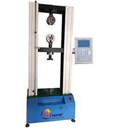
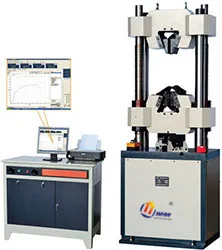
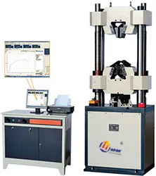
WEW300-600B Hydraulic Universal Testing Machine
Hydraulic Universal Testing Machine
- 最大试验力100KN / 300KN / 600KN / 1000KN
- 测试范围5-100KN / 12-300KN / 50-600KN / 50-1000KN
 WAW-100B · 2026-11-17 · +86 21 5748 2007
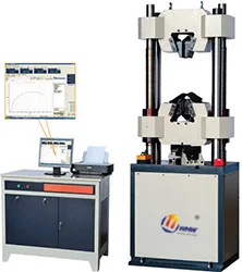
Electro-hydraulic Servo Universal Testing Machine
By submitting you agree to our privacy policy.
WAW-BG系列电液伺服万能试验机用于各种金属、非金属材料的拉伸、压缩、弯曲和剪切试验,以及一些产品的特殊试验,适用于冶金、建筑、轻工、航空、航天、材料、大专院校、科研单位等领域。
油缸采用:间隙密封,下置式主机,拉伸空间位于主机的上方,压缩、弯曲试验空间位于主机下横梁和工作台之间。
传动系统采用:下横梁升降电机经减速器、链传动机构、丝杠副传动,实现拉伸、压缩空间的调整。
液压系统采用:油箱内的液压油通过电机带动高压泵进入油路,流经单向阀、高压滤油器、压差阀组、伺服阀,进入油缸。计算机发出控制信号到伺服阀,控制伺服阀的开口和方向,从而控制进入油缸的流量,实现等速试验力、等速位移等的控制。
控制系统采用:实现了试验力、试样变形、横梁位移和试验进程的四种闭环控制;高分辨率达1/500000,全程不分档。
保护系统采用:当试验力超过最大试验力的3%时,过载保护,油泵电机停机;当活塞升起达到上极限位置时,行程保护,油泵电机停机。
二. WAW-BG系列电液伺服万能试验机性能特点:
1.下置式主机。
2.闭环控制。
3.高精度A/D模组,最高分辨率达1/500000,全程不分档。
4.过载保护和行程保护,有效保护电机的正常运转。
5.简单、可靠、稳定的液压系统。
6.测力范围高达2%-100%FS。
7.可定制试验机主机颜色。
三. WAW-BG系列电液伺服万能试验机技术特征:
产品型号MC009
WAW-100B
最大试验力
100KN
测试范围
2-100KN
测试准确度
±1%或±0.5%
实验级别
1级或0.5级
实验力分辨率
0.002KN
位移测量分辨率
0.01mm
变形测量精度
0.005mm
恒力、恒变形、恒位移控制范围
0.4%~100%FS
恒力、恒变形、恒位移控制精度
设定值小于10%FS时,设定值的±1.0%以内;设定值≥10%FS时,设定值的±0.5%以内
拉伸空间
550
压缩空间
380
活塞行程
150
圆试样钳口夹持直径
Φ6-Φ26
扁试样钳口夹持厚度
0-12
弯曲试验两点间距离
350
弯曲支滚宽度
100
弯曲支滚直径
Φ30
最大弯曲度
150
活塞最大移动速度
50mm/min
夹紧方式
手动夹紧
主机外形尺寸
720×580×1850
油源外形尺寸
950×700×1150
重量
1550kg
WAW-100B Electro-hydraulic Servo Universal Testing Machine supplied by CHWES. 23 key specifications available on request.
| 最大试验力 | 100KN |
|---|---|
| 测试范围 | 2-100KN |
| 测试准确度 | ±1%或±0.5% |
| 实验级别 | 1级或0.5级 |
| 实验力分辨率 | 0.002KN |
| 位移测量分辨率 | 0.01mm |
| 变形测量精度 | 0.005mm |
| 恒力、恒变形、恒位移控制范围 | 0.4%~100%FS |
| 恒力、恒变形、恒位移控制精度 | 设定值小于10%FS时,设定值的±1.0%以内;设定值≥10%FS时,设定值的±0.5%以内 |
| 拉伸空间 | 550 |
| 压缩空间 | 380 |
| 活塞行程 | 150 |
| 圆试样钳口夹持直径 | Φ6-Φ26 |
| 扁试样钳口夹持厚度 | 0-12 |
| 弯曲试验两点间距离 | 350 |
| 弯曲支滚宽度 | 100 |
| 弯曲支滚直径 | Φ30 |
| 最大弯曲度 | 150 |
| 活塞最大移动速度 | 50mm/min |
| 夹紧方式 | 手动夹紧 |
| 主机外形尺寸 | 720×580×1850 |
| 油源外形尺寸 | 950×700×1150 |
| 重量 | 1550kg |
* Generated by rule engine over the product database; for pre-selection only.
A universal testing machine comprises the load frame, drive system, load cell, displacement/extensometer measurement and closed-loop control. A servo motor and screw drive the crosshead (or a servo valve drives the actuator); the load cell converts force to a signal, the extensometer measures strain over the gauge length, and the controller follows the programmed rate while logging force–displacement–strain.
Software derives upper and lower yield strength (ReH/ReL), tensile strength Rm, elongation A, reduction of area Z and modulus E. Control modes include speed, force, displacement and strain; GB/T 228.1-2021 requires strain control in the yield region (method A) for lower uncertainty.
1. Tensile strength: Rm = Fmax/S0; a 10 mm bar (S0=78.5 mm²) breaking at 62.8 kN gives Rm ≈ 800 MPa.
2. Yield: Rp0.2 is interpolated from the extensometer curve at 0.2% non-proportional extension.
3. Elongation & reduction: A = (Lu−L0)/L0; Z = (S0−Su)/S0; L0=50, Lu=62.5 mm → A = 25%.
4. Friction coefficient: μ = F/N; at N = 100 N and F = 32 N, μ = 0.32. Four-ball results report PB (last non-seizure) and PD (weld) loads.
5. Wear rate: k = V/(F·s); obtain V from Δm/ρ. Typical specific wear rates run 10⁻⁸–10⁻⁶ mm³/(N·m).
| Standard | Title | Scope |
|---|---|---|
| GB/T 228.1-2021 | Metallic materials — tensile testing, room temperature | Tension |
| ISO 6892-1 | Tensile testing at room temperature | Export projects |
| ASTM E8/E8M | Tension testing of metallic materials | Americas |
| GB/T 7314-2017 | Compression testing at room temperature | Compression |
| GB/T 232-2010 | Bend testing of metallic materials | Bending |
| GB/T 3098.1-2010 | Mechanical properties of fasteners | Fasteners |
1. Frame capacity plus 20–30%: Φ32 rebar yields near 630 kN so choose 1000 kN; M30 proof load is about 550 kN so choose 600–1000 kN. Running at full scale accelerates load-cell fatigue.
2. Servo-hydraulic or electromechanical: ≥300 kN with high stiffness and long stroke (rebar, bolts, concrete) needs servo-hydraulic (WAW/WEW); ≤300 kN with tight speed control (plastics, composites) suits electromechanical frames (WDS).
3. Display, digital or PC-controlled: a digital readout for single values; PC control (the -C suffix) for stress-strain curves, reports and batch data.
4. Fixtures often matter more than the frame: ribbed grips for rebar, proof-load fixtures for bolts, wrap grips for cables. Poor alignment costs 2–3 percentage points of elongation.
5. Extensometers and options: contact or video extensometers for modulus, high-temperature furnaces and extensometers, large platens with displacement control for battery crush.
6. Foundation and safety: a 1000 kN frame needs an isolated concrete base, guard doors and e-stops; hydraulic units need oil-temperature management.
| Series | Type | Force range | Typical specimens |
|---|---|---|---|
| WDS-1G to 300G | Electromechanical | 1–300 kN | Plastics, composites, small parts |
| WEW-100D to 1000D | Hydraulic, digital | 100–1000 kN | Rebar, bolts, metals |
| WEW-300C to 2000C | Hydraulic, PC | 300–2000 kN | High-strength bolts, forgings |
| WAW-100 to 1000 | Servo-hydraulic | 100–1000 kN | Rate-controlled acceptance |
| WAW-300C to 2000C | Servo-hydraulic, PC | 300–2000 kN | Bridges, nuclear components |
| WES-300C to 2000C | Compression | 300–2000 kN | Concrete, blocks |
| MMW-1A / MRS-10W | Friction and wear | — | Lubricants, coatings |
Three acceptance checks: verify force at 20/50/80% with a standard load cell; check alignment so a standard specimen breaks mid-gauge; run three identical specimens and look at scatter.
Specimen. Proportional (L₀ = 5.65√S₀) or non-proportional specimens to GB/T 228.1; transition radius R ≥ 5 mm; Ra ≤ 1.6 µm with work-hardened layers removed.
Measurement. Width and thickness at three positions within the gauge length, use the minimum for S₀; below 1 mm use optical or 0.001 mm micrometers.
Loading. 5–30 MPa/s in the elastic range, 0.00025/s strain rate at yield per method A, up to 0.0067/s in hardening; log at 100 Hz or more to catch yield serrations.
Evaluation. ReH is the first peak, ReL the lowest point, Rm the maximum force over S₀, A from the final gauge length (offset method), Z from the minimum fracture diameter.
Quality control. Daily check with a reference specimen, monthly force calibration with a class 0.3 proving instrument, half-yearly extensometer calibration, 23 ± 5 °C.
HOTHydraulic Universal Testing Machine
 HOT
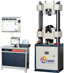
Hydraulic Universal Testing Machine
 HOT
Hydraulic Universal Testing Machine