 HOT
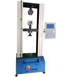
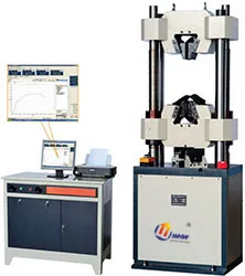
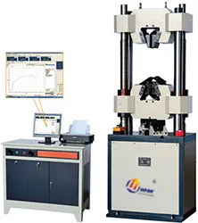
WEW300-600B Hydraulic Universal Testing Machine
Hydraulic Universal Testing Machine
- 最大试验力100KN / 300KN / 600KN / 1000KN
- 测试范围5-100KN / 12-300KN / 50-600KN / 50-1000KN
 JB-300B/500B · 2026-11-17 · +86 21 5748 2007
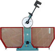
Impact Testing Machine
By submitting you agree to our privacy policy.
JB-B系列冲击试验机用来对金属材料在动负荷下抵抗冲击的性能进行检验,是冶金、机械制造等单位必备的检测仪器,也是科研单位进行新材料研究不可缺少的测试仪器。该系列机型也是目前市场上使用普遍的冲击试验机。
技术特点
1、试验机主机为单支承柱式结构,悬臂式挂摆方式,摆锤锤体U型;
2、冲击刀采用螺钉安装固定,更换简单方便;
3、试样简支梁式支承;
4、主机装有安全防护销,并且配备了安全防护网;
5、试验机为半自动控制,扬摆、挂摆、冲击、放摆均为电气控制,并能利用冲断试样后的剩余能量自动扬摆做好下次试验准备,特别适用于连续做冲击试验的试验室和大量做冲击试验的冶金、机械制造等部门;
6、试验机符合国标GB/T3803-2002《摆锤式冲击试验机的检验》,按国标GB/T229-2007《金属夏比缺口冲击试验方法》对金属材料进行冲击试验。JB-300B/500B型为刻度盘显示冲击试验机;
技术参数:
型号
JB-300B
JB-500B
显示方式
度盘显示
冲击能量
150/300J
250/500J
摆轴中心至冲击点距离
750mm
800mm
冲击速度
5.2m/s
5.4 m/s
摆锤预扬角
150°
试样支座跨距
40+0.2mm
钳口圆角
R1-1.5mm
冲击刀刃圆角
R2-2.5mm,R8±0.05mm
试样尺寸
10(7.5、5、2.5)mm×10mm×55mm
JB-300B/500B Impact Testing Machine supplied by CHWES. 9 key specifications available on request.
| 显示方式 | 度盘显示 |
|---|---|
| 冲击能量 | 150/300J / 250/500J |
| 摆轴中心至冲击点距离 | 750mm / 800mm |
| 冲击速度 | 5.2m/s / 5.4 m/s |
| 摆锤预扬角 | 150° |
| 试样支座跨距 | 40+0.2mm |
| 钳口圆角 | R1-1.5mm |
| 冲击刀刃圆角 | R2-2.5mm,R8±0.05mm |
| 试样尺寸 | 10(7.5、5、2.5)mm×10mm×55mm |
* Generated by rule engine over the product database; for pre-selection only.
A universal testing machine comprises the load frame, drive system, load cell, displacement/extensometer measurement and closed-loop control. A servo motor and screw drive the crosshead (or a servo valve drives the actuator); the load cell converts force to a signal, the extensometer measures strain over the gauge length, and the controller follows the programmed rate while logging force–displacement–strain.
Software derives upper and lower yield strength (ReH/ReL), tensile strength Rm, elongation A, reduction of area Z and modulus E. Control modes include speed, force, displacement and strain; GB/T 228.1-2021 requires strain control in the yield region (method A) for lower uncertainty.
1. Tensile strength: Rm = Fmax/S0; a 10 mm bar (S0=78.5 mm²) breaking at 62.8 kN gives Rm ≈ 800 MPa.
2. Yield: Rp0.2 is interpolated from the extensometer curve at 0.2% non-proportional extension.
3. Elongation & reduction: A = (Lu−L0)/L0; Z = (S0−Su)/S0; L0=50, Lu=62.5 mm → A = 25%.
4. Friction coefficient: μ = F/N; at N = 100 N and F = 32 N, μ = 0.32. Four-ball results report PB (last non-seizure) and PD (weld) loads.
5. Wear rate: k = V/(F·s); obtain V from Δm/ρ. Typical specific wear rates run 10⁻⁸–10⁻⁶ mm³/(N·m).
| Standard | Title | Scope |
|---|---|---|
| GB/T 228.1-2021 | Metallic materials — tensile testing, room temperature | Tension |
| ISO 6892-1 | Tensile testing at room temperature | Export projects |
| ASTM E8/E8M | Tension testing of metallic materials | Americas |
| GB/T 7314-2017 | Compression testing at room temperature | Compression |
| GB/T 232-2010 | Bend testing of metallic materials | Bending |
| GB/T 3098.1-2010 | Mechanical properties of fasteners | Fasteners |
1. Frame capacity plus 20–30%: Φ32 rebar yields near 630 kN so choose 1000 kN; M30 proof load is about 550 kN so choose 600–1000 kN. Running at full scale accelerates load-cell fatigue.
2. Servo-hydraulic or electromechanical: ≥300 kN with high stiffness and long stroke (rebar, bolts, concrete) needs servo-hydraulic (WAW/WEW); ≤300 kN with tight speed control (plastics, composites) suits electromechanical frames (WDS).
3. Display, digital or PC-controlled: a digital readout for single values; PC control (the -C suffix) for stress-strain curves, reports and batch data.
4. Fixtures often matter more than the frame: ribbed grips for rebar, proof-load fixtures for bolts, wrap grips for cables. Poor alignment costs 2–3 percentage points of elongation.
5. Extensometers and options: contact or video extensometers for modulus, high-temperature furnaces and extensometers, large platens with displacement control for battery crush.
6. Foundation and safety: a 1000 kN frame needs an isolated concrete base, guard doors and e-stops; hydraulic units need oil-temperature management.
| Series | Type | Force range | Typical specimens |
|---|---|---|---|
| WDS-1G to 300G | Electromechanical | 1–300 kN | Plastics, composites, small parts |
| WEW-100D to 1000D | Hydraulic, digital | 100–1000 kN | Rebar, bolts, metals |
| WEW-300C to 2000C | Hydraulic, PC | 300–2000 kN | High-strength bolts, forgings |
| WAW-100 to 1000 | Servo-hydraulic | 100–1000 kN | Rate-controlled acceptance |
| WAW-300C to 2000C | Servo-hydraulic, PC | 300–2000 kN | Bridges, nuclear components |
| WES-300C to 2000C | Compression | 300–2000 kN | Concrete, blocks |
| MMW-1A / MRS-10W | Friction and wear | — | Lubricants, coatings |
Three acceptance checks: verify force at 20/50/80% with a standard load cell; check alignment so a standard specimen breaks mid-gauge; run three identical specimens and look at scatter.
Specimen. Proportional (L₀ = 5.65√S₀) or non-proportional specimens to GB/T 228.1; transition radius R ≥ 5 mm; Ra ≤ 1.6 µm with work-hardened layers removed.
Measurement. Width and thickness at three positions within the gauge length, use the minimum for S₀; below 1 mm use optical or 0.001 mm micrometers.
Loading. 5–30 MPa/s in the elastic range, 0.00025/s strain rate at yield per method A, up to 0.0067/s in hardening; log at 100 Hz or more to catch yield serrations.
Evaluation. ReH is the first peak, ReL the lowest point, Rm the maximum force over S₀, A from the final gauge length (offset method), Z from the minimum fracture diameter.
Quality control. Daily check with a reference specimen, monthly force calibration with a class 0.3 proving instrument, half-yearly extensometer calibration, 23 ± 5 °C.
HOTHydraulic Universal Testing Machine
 HOT
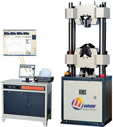
Hydraulic Universal Testing Machine
 HOT
Hydraulic Universal Testing Machine