 HOT
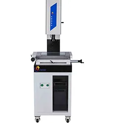
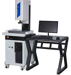
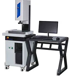
YR3020CNC-T CNC Vision Measuring Machine
CNC Vision Measuring Machine
- 测量工件尺寸300*200*180mm
- X/Y轴测量精度3+L/200um
 YR120100-M · 2026-11-17 · +86 21 5748 2007
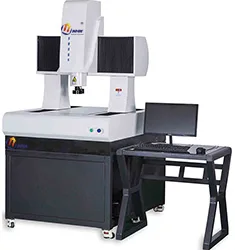
Gantry Vision Measuring Machine
By submitting you agree to our privacy policy.
YR120100-M龙门式全自动三维影像测量仪采用移动桥式结构,三轴CNC全自动控制系统和精密花岗岩机台实现精密的测量.采用开放式光栅尺提供高稳定性的测量精度.它专为大尺寸测量而设计,它适用于PCB、LCD、钣金、航空航天等行业的大行程测量。它采用移动桥式结构,汇集了行业内先进的设计理念,以完善的设计和严格的生产流程控制,确保机台的精度和稳定性。
一、技术参数:
测量工件尺寸:1200*1000mm;
Z轴高度:300mm;
光学放大倍数:0.7~4.5X;
系统放大倍数:21~200X;
X/Y测量精度:3.5+L/200um;
Z轴测量精度:5+L/200um;
X/Y轴运行速度:280mm/s;
Z轴运行速度:100mm/s;
承重:80kg;
整机重量:2800kg;
电源电压:200~240V,50/60Hz,单相,700W;
工作环境温度:20°C±2°C;
工作环境湿度:30~80%;
工作环境振动:<0.002g,<15Hz;
二、机器配置:
三轴CNC自动控制;
底座/立柱材质:00级精密花岗岩,平面度3um;
导轨:台湾HITIN精密线性滑轨;
光栅尺:贴片式0.5um分辨率精密光栅尺;
X/Y轴电机:日本三菱精密伺服电机;
Z轴电机:日本三菱精密伺服电机(直流带抱闸);
CCD:海康威视千兆网彩色工业数字相机;
镜头:6.5:1可变倍镜头;
表面光源:五环八区LED冷光源,256级亮度可调节;
轮廓光源:LED冷光源,256级亮度可调节;
三、软件系统:
CNC智能测控系统;
CNC4000型电控系统;
四、标配:
电脑;
出厂检验报告;
合格证;
保修卡;
五、选配:
三维测头系统:英国雷尼绍三维MCP测头;
三维测针:英国雷尼绍三维红宝石1MM+2MM测针;
六、软件功能:
几何量测量:点、线、圆(最大、最小和平均)、弧、样条曲线、椭圆、矩形、四边形、槽、R角、环、间距、距离、点群等;
构建:中心点、极值点、端点、交点、两点连线、平行线、垂线、切线、平分线、中心线、合并、轮廓分割、半径画圆、三线内切圆、两线半径内切圆等。
测量工具:绘图点、最近边缘点、聚焦点、圆形框取点、最佳边缘点、最近点、整体提取、多段提取、纹理分割、多段纹理分割、电子卡尺、快速整理取圆、开放轮廓线、最大闭合轮廓线、最近闭合轮廓线。
形位公差测量:直线度、圆度、位置度、平行度、垂直度、倾斜度、同心度等。
坐标系:夹具定位坐标系、点线、两点X、两点Y、三点、两线、图像配准坐标系;平移、旋转、手工调整坐标系。
生成任务:进行全自动批量测量,并支持自动和手工交互操作。
变倍技术:镜头可手动变倍,变倍后无需重新校正。
光源控制:自动控制,支持自动打光。支持表面光五环八区、轮廓光的各区段自动控制。
自动聚焦:快速自动聚焦,聚焦测量高度。
报表:Word、Excel(模板定制)、PDF、DXF、AutoCAD导入导出。
任务控制:自动记录.rst格式文件任务信息,直接打印数据。
任务输出:任务数据输出到csv文件;指定文件目录。
SPC数据统计:导入rst文件,可进行有效的品管控制。
基元数据及区域:实时显示当前正在测量的基元数据;分类显示正常基元,超差基元,未测量基元等等。
全景扫描:任意选择区域进行影像的扫描拼图。
图纸数据比对:可载入图纸与测量数据进行比对。
试验筛:自动取样扫描试验筛,生成任务,运行结果直接分析输出。
温度补偿:根据环境温度与标准温度差值,计算膨胀系数,使得结果更精确。
聚焦测高:用聚焦方式测量高度差。
自动轮廓提取:给定起始结束点,对指定轮廓进行提取。
显示边缘图:显示图像的边缘轮廓,快速查看边缘情况。
十字线提取模式:多种显示模式,十字,井字,圆形,网格,方便快速比对。
导航:图片导航,类似于电子地图,可快速定位。
导入CAD图纸:可导入DXF图纸,与CAD互相导入导出,完成图形处理。
3D显示:显示图像的三维状态。
多语言切换:简体、繁体、英语、日语、韩语。
镜头标定:自动镜头校准,省去繁琐的完全标定步骤。
YR120100-M Gantry Vision Measuring Machine supplied by CHWES. 24 key specifications available on request.
| 测量工件尺寸 | 1200*1000mm |
|---|---|
| Z轴高度 | 300mm |
| 光学放大倍数 | 0.7~4.5X |
| 系统放大倍数 | 21~200X |
| X/Y测量精度 | 3.5+L/200um |
| Z轴测量精度 | 5+L/200um |
| X/Y轴运行速度 | 280mm/s |
| Z轴运行速度 | 100mm/s |
| 承重 | 80kg |
| 整机重量 | 2800kg |
| 电源电压 | 200~240V,50/60Hz,单相,700W |
| 工作环境温度 | 20°C±2°C |
| 工作环境湿度 | 30~80% |
| 工作环境振动 | <0.002g,<15Hz |
| 二、机器配置 | 三轴CNC自动控制 |
| 底座/立柱材质 | 00级精密花岗岩,平面度3um |
| 导轨 | 台湾HITIN精密线性滑轨 |
| 光栅尺 | 贴片式0.5um分辨率精密光栅尺 |
| X/Y轴电机 | 日本三菱精密伺服电机 |
| Z轴电机 | 日本三菱精密伺服电机(直流带抱闸) |
| CCD | 海康威视千兆网彩色工业数字相机 |
| 镜头 | 6.5:1可变倍镜头 |
| 表面光源 | 五环八区LED冷光源,256级亮度可调节 |
| 轮廓光源 | LED冷光源,256级亮度可调节 |
* Generated by rule engine over the product database; for pre-selection only.
Vision measuring systems replace contact metrology with imaging: backlight turns part edges into a high-contrast silhouette, while surface and coaxial light reveal bores, blind holes and steps. After capture, software extracts sub-pixel edges, fits lines, circles and arcs by least squares, establishes a part coordinate system (3-2-1 or best-fit) and computes distances, angles, concentricity and position tolerance.
The stage is driven by servo motors and precision screws with linear encoder feedback (0.1–1 µm). CNC models automate the move–capture–measure sequence for batch inspection. Accuracy is typically stated as U = 2.0 + L/200 µm at 20 ± 2 °C.
1. Indication error: commonly E = (2.5 + L/150) µm (L in mm); at L = 200 mm, E ≈ 3.83 µm, verified with a glass ruler along the diagonals.
2. Pixel size: field width ÷ active pixels; an 8 mm field on 1280 px gives 6.25 µm/px, improved to 1/10 px by sub-pixel algorithms.
3. Circle fit: σ(diameter) ≈ σpoint/√n — use ≥16 points per least-squares circle.
4. True position: deviation Δ = 2√(Δx² + Δy²) versus tolerance zone φt; Δx=0.02, Δy=0.015 mm gives Δ = 0.05 mm.
5. Thermal correction: 100 mm of steel changes 1.2 µm per °C (α≈11.5×10⁻⁶/°C) — apply on the shop floor.
| Standard | Title | Use |
|---|---|---|
| GB/T 24762-2009 | GPS — acceptance and reverification tests for imaging instruments | Acceptance, annual check |
| JJF 1318-2011 | Calibration specification for vision measuring instruments | Calibration |
| ISO 10360-7 | Acceptance tests for CMMs with imaging probing systems | Export projects |
| VDI/VDE 2617 | Accuracy of coordinate measuring machines | Accuracy rating |
| GB/T 1958-2017 | GPS — verification of geometrical tolerance | GD&T |
1. Calculate travel first: maximum part envelope plus fixture plus approach margin, then add 20%. Sizing on the part alone is the classic mistake. YRVMS covers 150×100 to 1200×1500; larger parts need YRVMS5030 or gantry models.
2. Three accuracy numbers, not one: indication error (E), repeatability (R) and scale resolution. E = 2.5+L/200 µm is standard, 1.8+L/300 µm for precision work; a 0.001 mm display means nothing on its own.
3. Manual, motorised or CNC: manual (YRVMS1510F) for sampling, motorised (YRVMS2010E and up) for repetitive batches, CNC (YRVMS3020CNC and up) for programmed multi-feature and unattended runs.
4. Optics and lighting decide capability: 0.7–4.5× zoom with bi-telecentric optics for planar dimensions; laser or touch probe for height, blind holes and deep slots; coaxial light for polished metal, backlight for transparent parts.
5. Software, three questions: can it build a coordinate system from drawing datums rather than by eye, does it output FAI/PPAP sheets, and does it support SPC and Excel export.
6. In-line inspection is a different machine: use YR-MV for cycle-time-driven 100% inspection instead of a measuring machine.
| Series | Drive | Travel (mm) | Typical use |
|---|---|---|---|
| YRVMS1510F | Manual | 150×100 | Small-part sampling, teaching |
| YRVMS2010E / 2515F | Motorised / manual | 200×100 / 250×150 | Connectors, precision hardware |
| YRVMS3020CNC / 4030CNC | CNC | 300×200 / 400×300 | 3C FAI, batch programming |
| YRVMS5030 / 5030CNC | CNC | 500×300 | Mid-size structural parts |
| YRVMS120150 | Gantry CNC | 1200×1500 | Sheet and large contours |
| YR-MV1080 / 7070 | Dedicated vision | Custom | In-line 100% inspection |
| YR-QVS series | Flash measurement | Small field | One-click multi-dimension |
Acceptance advice: verify E with a glass scale after installation, check R by measuring the same part ten times, then compare against a part with known CMM results; the deviation should stay within E.
Environment. 20 ± 2 °C, 40–60% RH, vibration-free; warm up 30 minutes; soak parts at least 2 hours (4 for large parts).
Calibration. Measure a glass scale or ceramic gauge block at near and far positions in X/Y/Z; perform ISO 10360-7 probing in seven directions with a length standard.
Measurement. Establish the coordinate system (plane–line–point or 3-2-1); take at least five points per feature (six for a circle, eight for a large circle); avoid chamfered edges; repeat each feature three times.
Verification. Check daily with a known artefact (50 mm block, certified circle); recalibrate when deviation exceeds one third of MPE.
Uncertainty. Dominated by temperature (11.5 × 10⁻⁶/°C × L), encoder error, edge algorithm and clamping repeatability; state U at k = 2.
HOTCNC Vision Measuring Machine
 HOT
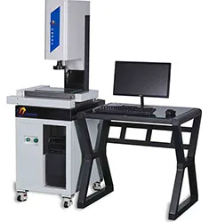
CNC Vision Measuring Machine
 HOT
CNC Vision Measuring Machine