 HOT
 YR-1S · 2026-11-17 · +86 21 5748 2007
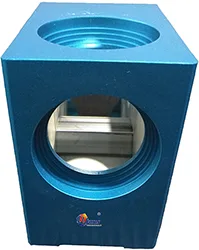
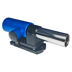
YR-1S Digital Autocollimator (30 m,1″)
Digital Autocollimator · 30 m,1″
型番YR-1S
- 1)测角范围0~800″
- 2)读数鼓格值1″
- 3)目视读数不稳定性<0.5″
- 4)示值误差10′(测微鼓轮2-8mm)范围内≤3″;任意1′(测微鼓轮2-8mm) 范围内≤1.5″
By submitting you agree to our privacy policy.
01
製品概要
一.1秒精密测微自准直仪主要用途:
1秒精密测微自准直仪分单向(YR-1D)和双向(YR-1S),该仪器是一种高精度测角用的精密光学仪器。它广泛用于测量导轨的直线性、精密平板的平面度、基面之间的垂直度和平行度、精密轴系的晃动误差等;同时还可以来测量各种棱镜的角度差和平镜的平行差以及测量检验各种棱镜、平镜与装配基准面之间的角度误差。因此该仪器可以在机械制造业、精密仪器制造业、计量室、光学实验室、光学冷加工车间及光学仪器的装配、调整、检验等多方面广泛得到应用。
二1秒精密测微自准直仪技术参数:
1.仪器的规格与参数:
1)测角范围:0~800″
2)读数鼓格值:1″
3)目视读数不稳定性:<0.5″
4)示值误差:
10′(测微鼓轮2-8mm)范围内≤3″;
任意1′(测微鼓轮2-8mm) 范围内≤1.5″
5)准直物镜:焦距:258mm,入瞳直径:Φ40mm
6)显微物镜:焦距:27.45mm,放大倍率:4倍
7)测微目镜:
焦距:16.7mm,放大倍率15倍,
视场:8mm×8mm,视度调节:±5屈光度
8) 组合焦距:1031.324mm
9)仪器放大倍率:61.8倍
10)最大测量距离:30m(视场≮2′)
11)视轴与镜管机械轴平行度:<±20″
12)视轴与基底座平面(去掉三个调平螺钉后)的平行度:<1′
13)圆水泡规格:8′;置平精度:4′
14)照明灯电压:6v ;功率:2~5w
15)仪器外形尺寸:490mm×162mm×180mm
16)仪器重量:7.8Kg
2.楔形镜规格与参数
1)镜面通光孔径:Φ46mm,中心反射面直径:Φ25mm
2)楔形镜角值:10′±30″(指内外反射像的夹角)
楔角标定精度:<1″
3)楔形镜两面形误差:<1/10光圈(1/20波长)
4)全反射面对底面垂直度:<20″
全反射面对侧面垂直度:<1′
5)外形尺寸:106mm×74mm×125mm
三、1秒精密测微自准直仪为了提高仪器的测量精度,应注意以下几点:
(1)仪器及被测量零件应放在较稳定的工作台上。工作环境应力求温度恒定,做测件与仪器中间不得有抖动的气流,如通风口、暖气片、电烙铁、台灯、人体温度等,应尽量避免其影响。
(2)观察表面镀反射膜的反射镜自准像应选择小功率灯泡,观察表面未镀反射膜的光学零件(如平行平板、棱镜等)的自准像则应选择功率大的灯泡,该仪器可使用6v5w以下的小灯泡。
(3)在可能的情况下每一个自准像多次瞄准所读取的读数取平均值计算可降低瞄准误差,提高仪器精度。一般取3~5次。
四.1秒精密测微自准直仪仪器的维护和保养
1.该仪器系精密光学仪器,应该由专人保管。使用者应了解仪器的原理、性能及使用方法。使用存放应十分小心,防止碰撞及振动。应保持工作环境的清洁及温度稳定。
2.仪器出厂时各部份均保证了良好的性能,除可调部份一般不能随意拆开调整。如发生故障应由有经验的人检修或送回制造厂家检修。
3.镜头及目镜的外露玻璃部分切忌手摸,应尽量少擦。如有灰尘可用软毛刷轻轻扫掉。如有印迹可用脱脂棉或镜头纸蘸少量的酒精乙醚的混合物或丙酮等进行擦拭。
4.镜管及其它外露表面可用溶剂汽油清擦干净。仪器使用后应盖上护盖,若长时间不用应装入箱内并放平于干燥、温度适当之处进行保管。
五、YR-1S双向精密自准直仪选配附件:
1.带磁反射镜(特殊定货)
2.光学直角器(特殊定货)
3.激光找准器(特殊定货)
4、专用升降平台(特殊定货)
5、专用三角架(特殊定货)
六、自准直仪的典型应用:
1.直线度测试:直线度测量和验证是自准直仪在机械制造行业典型的应用之一。本系列准直仪测试直线度具有精度高、重复性好和双方向同时检测的优点。在直线度测量中,借助一个桥板将角度量转化为位移量进行测量,测量中使用首尾搭接法通过在整个测量行程内分段移动桥板完成测量过程。如图:
2.自准直仪平面度测试:平面度测量和验证是自准直仪进行直线度测量的拓展应用。通过对待测平面的若干直线进行测量(通常测量为米字型或者网格分布),最后将测试结果进行计算分析。整个测量过程根据精度的要求和平面尺寸选用2个或3个不同尺寸的测量桥板进行配合使用。如图:
3.自准直仪垂直度测试:垂直度测量和验证原理为采用自准直仪分别测量两条待测导轨的直线度后,根据测量结果分析出两条导轨的共面垂直度偏差,测量中基准的传递采用直角转像镜(光学五棱镜)进行。如图,先测试一条导轨的直线度并作为基准线,然后将直角转像镜放置在另一导轨位置后进行第二条直线测量并作为测量线。使用基准线的直线度包容区旋转90度后对测量线的直线度曲线进行包容后的结果即为垂直度偏差值。
4.自准直仪平行度测试:平行度测量和验证的基本原理是采用自准直仪分别测量两条待测导轨的直线度后,根据测量结果计算出两条导轨的共面平行度偏差,测量中的基准传递是采用直角转像镜(光学五棱镜)进行。如图,首先测量一条导轨的直线度并作为基准线,随后将直角转像镜移动至另一导轨位置后进行第二条直线测量并作为测量线。使用基准线的直线度包容区平移后对测量线的直线度曲线进行包容后的结果即为平行度偏差值。
5.自准直仪位置不确定度测试:自准直仪结合多面棱体和检测的旋转平台可以进行角度的不确定度检测。
6.多个自准直仪组合对光学块进行比较测量。(可以组合成测角仪)
YR-1S Digital Autocollimator (30 m,1″) supplied by CHWES. 25 key specifications available on request.
02
仕様
| 1)测角范围 | 0~800″ |
|---|---|
| 2)读数鼓格值 | 1″ |
| 3)目视读数不稳定性 | <0.5″ |
| 4)示值误差 | 10′(测微鼓轮2-8mm)范围内≤3″;任意1′(测微鼓轮2-8mm) 范围内≤1.5″ |
| 5)准直物镜 | 焦距:258mm,入瞳直径:Φ40mm |
| 6)显微物镜 | 焦距:27.45mm,放大倍率:4倍 |
| 焦距 | 16.7mm,放大倍率15倍 |
| 视场 | 8mm×8mm,视度调节:±5屈光度 |
| 8) 组合焦距 | 1031.324mm |
| 9)仪器放大倍率 | 61.8倍 |
| 10)最大测量距离 | 30m(视场≮2′) |
| 11)视轴与镜管机械轴平行度 | <±20″ |
| 13)圆水泡规格 | 8′ |
| 置平精度 | 4′ |
| 14)照明灯电压 | 6v |
| 功率 | 2~5w |
| 15)仪器外形尺寸 | 490mm×162mm×180mm |
| 16)仪器重量 | 7.8Kg;2.楔形镜规格与参数 |
| 1)镜面通光孔径 | Φ46mm,中心反射面直径:Φ25mm |
| 2)楔形镜角值 | 10′±30″(指内外反射像的夹角) |
| 楔角标定精度 | <1″ |
| 3)楔形镜两面形误差 | <1/10光圈(1/20波长) |
| 4)全反射面对底面垂直度 | <20″ |
| 全反射面对侧面垂直度 | <1′ |
| 5)外形尺寸 | 106mm×74mm×125mm |
* Generated by rule engine over the product database; for pre-selection only.
03
測定原理
An autocollimator projects an illuminated cross-line as a parallel beam onto an external mirror. The mirror returns the beam, which re-images on the reticle or a CCD/CMOS sensor. If the mirror tilts by θ, the return image shifts by s = 2f·tanθ — the angle is doubled optically and magnified by the focal length.
Photoelectric readout (CCD/CMOS centroiding or PSD differential detection with software subdivision) reaches 0.1″ resolution. Dual-axis models read horizontal and vertical tilt simultaneously; large-field versions such as the HXDS15-4000 (4000×3000″) image a wide angular range for dynamic measurements.
Stepping a mirror bridge along a guideway converts per-step tilts θi into elevation differences hi = L·tanθi for straightness and flatness; with polygons or multi-tooth tables the same instrument calibrates circular indexing.
04
Process animation
- Setup: mount the mirror on a bridge of span L at the start of the guideway.
- Zeroing: adjust the autocollimator until the cross image centres, record the initial reading.
- Step: advance the bridge by L each station, logging θi (both axes on dual-axis models).
- Evaluate: accumulate hi = L·tanθi and rate straightness or flatness by end-point or minimum-zone methods.
- Indexing: with a polygon, successive face readings give the index error; issue the report.
05
Calculation & formulas
1. Angle-image relation: θ = s/(2f); with f = 500 mm and s = 5 µm, θ ≈ 1.03″ (1″ ≈ 4.85 µrad).
2. Resolution: 0.1″ corresponds to s ≈ 0.485 µm at f = 500 mm — pixels ≤5 µm plus 1/10 subdivision.
3. Elevation step: h = L·tanθ; a 100 mm bridge at 2″ gives h ≈ 0.97 µm.
4. End-point straightness: cumulative deviations Δi = Σhk − (i/n)Σh, error f = max(Δ) − min(Δ); the minimum-zone method rotates the datum per convex/concave/alternating criteria.
5. Indexing: per-face errors φj minus nominal; the closure Σφ = 0 checks the full circle.
06
規格
| Standard | Title | Scope |
|---|---|---|
| JJG 202-2007 | Verification regulation of autocollimators | Indication error and resolution |
| GB/T 11336-2004 | Detection of straightness error | Guideway and surface-plate straightness |
| GB/T 1958-2017 | GPS — detection and evaluation of geometrical deviations | Flatness, squareness and other form errors |
| ISO 230-1 | Machine tools — geometric accuracy tests | Machine acceptance |
| JJG 283-2007 | Multi-tooth indexing table verification | Circular indexing calibration |
Accredited labs must also hold 20±0.5 °C and vibration isolation, with instrument error within the 0.5″/1″ class.
07
選定ガイド
1. Resolution decides acceptance capability: 0.1″ (HXJL300-0.1, HXJL300U-0.1, HXJL300UH-0.1) for precision machines, rotary tables and laboratory standards; 0.2–0.3″ for general machine acceptance; 0.5–1″ (HXM series) for on-site alignment and long-range monitoring.
2. Distance decides aperture: 5–10 m with HXM2010/HXJL200; 20–30 m with HXM2020/HXM3030; 35–40 m with HXM3540; 50 m baseline with HXM4050M-1. Mirror aperture and light budget matter more as distance grows.
3. Single or dual axis: single-axis HXJL for one-direction straightness; dual-axis HXM for both directions and polygon indexing.
4. Dynamic work: HXDS15-4000 with a large field and high sampling rate for rotary-table oscillation, shaker tables and thermal drift.
5. Accessories: mirror bridges at 50/100/200 mm span, 12/24/36-face polygons, pentaprism for squareness, intermediate targets for long runs, thermal hoods for workshops.
6. Software and compliance: end-point, minimum-zone and least-squares evaluation with ISO 230-1 reports; labs also need the standard-artefact interface for verification.
| Model | Resolution | Distance | Typical use |
|---|---|---|---|
| HXJL300UH-0.1 | 0.1″ | 0–10 m | Precision tables, lab standards |
| HXJL300U-0.1 / HXJL300-0.1 | 0.1″ | 0–10 m | Precision guideways and plates |
| HXJL300-0.2 / -0.3 | 0.2–0.3″ | 0–10 m | General machine acceptance |
| HXM2010 / HXM2020 | 0.5–1″ | 10–20 m | Mid-size gantry, moulding machines |
| HXM3030 / HXM3540 | 0.5–1″ | 30–40 m | Large gantry, marine parts |
| HXM4050M-1 | 1″ | 50 m | Long guideways, cross-shop datums |
| HXDS15-4000 | Dynamic dual-axis | Large field | Table oscillation, vibration |
Common mistakes: using a 1″ unit to trend a 0.02 mm/m guideway; ignoring bridge sag under mirror weight; not controlling air currents and floor vibration, so readings never settle.
08
試験方法
Environment: 20±0.5 °C (±2 °C on the floor with compensation), shield air currents and sunlight; soak the instrument and bridge for 30 minutes on an isolated base.
Straightness procedure: ① clean the guideway and set the bridge span L; ② zero at the first station after 10 minutes of warm-up; ③ step by exactly L (within 0.5 mm), logging both axes; ④ evaluate by end-point and minimum-zone methods and report the larger; ⑤ record span, temperature and uncertainty (typically U ≈ 0.5″ + 2% of reading).
Intermediate checks: monthly 12-face polygon closure (Σ = 0, residual ≤0.3″); send standards out every two years.
Pitfalls: span errors feed straight into height differences; air currents jitter the centroid; thermal gradients bend long guideways optically — measure morning and afternoon and average.
09
Industry applications
- Machine tools: gantry and boring-mill guideway straightness, column and spindle squareness, table flatness to ISO 230-1 and GB/T 11336; repeatability ≤1 µm over 24 m with the end-point method.
- Metrology institutes: surface-plate flatness, cross-checks with electronic levels, small-angle standard build-up; indication error within ±0.5″/±1″ per JJG 202-2007.
- Indexing and rotary tables: multi-tooth tables, optical and CNC rotary tables, RV reducer backlash; full-circle checks with 12/24/36-face polygons, indexing error ≤±1″.
- Semiconductor stages: micro-angle feedback and thermal drift monitoring on air-bearing and wafer stages, resolution ≤0.01″ at ≥10 Hz.
- Inertial navigation and optics: reference-mirror alignment and angle transfer for gyro platforms, theodolites and interferometers.
- Energy equipment: turbine bearing alignment, wind-turbine flange squareness, long hydro shaft lines.
- Rail and elevators: guide-rail straightness and twist, body datum flatness, often at 30–50 m working distance.
- Research and teaching: optical bench levelling and micro-angle measurement.
10
Price and lead time for this model
同シリーズ
すべて見る→Photoelectric Autocollimators
HOT HOT
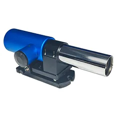
MC030-MAT200/38/1 Photoelectric Autocollimator (10 m1″)
Photoelectric Autocollimator · 10 m1″
- 型号MC030-MAT200/38/1
- 物镜焦距200mm
MC030-MAT200/38/0.5 Photoelectric Autocollimator (10 m0.5″)
Photoelectric Autocollimator · 10 m0.5″
- 型号MC030-MAT200/38/0.5
- 物镜焦距200mm