 HOT
 MMAS-8 · 2026-11-17 · +86 21 5748 2007
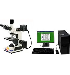
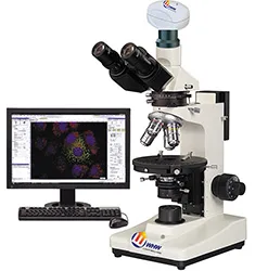
MMAS-8 Metallurgical Microscope (正置透反)
Metallurgical Microscope · 正置透反
型番MMAS-8
- 物镜长距平场消色差物镜(无盖玻片)PL 5X/0.12
- 放大倍数50~600X
- 目镜筒三目镜,倾斜30度,(内置检偏振片,可进行切换)
- 落射照明系统6V 20W卤素灯,亮度可调
By submitting you agree to our privacy policy.
01
製品概要
MMAS-8透反射(双色)金相显微镜测量分析系统配置透反射照明系统,长距平场消色差物镜(无盖玻片)、大视野目镜和内置偏光观察装置,光学系统成像清晰,视野广阔,适用于工矿企业,高等院校及科研等机构作材料内部组织结构观察。MMAS-8系统配备了研润自主研发的MMAS测量分析系统以及MOS高端光学系统。
一、技术特点:
1、观察系统:铰链式观察镜筒,30度倾斜,单视度可调。WF10X大视野平场目镜,视场范围直径18mm。10X分化目镜,视场范围直径18mm,用于校正中心。
2、机械载物台:双层机械式载物台,尺寸160*140mm;移动范围75*50mm。
3、落射照明系统:6V,20W卤素灯,亮度可调。内置视场光阑、孔径光阑、黄蓝绿红滤色片转换装置,插入式起偏振器。
4、透射照明系统:内置式6V,20W卤素灯,亮度可调。集光器:带视场光栏集光器;聚光镜:阿贝聚光镜NA1.25,升降上下可调。
5、选配件:
5.1大视野目镜:WF16X(直径11mm);
5.2分划板:10X(直径18mm),格值0.1mm/格;
5.3长距平场消色差物镜(无盖玻璃):PLL20X/0.4、PLL50X/0.7、PLL80X/0.8、PLL100X/0.85(弹簧);
5.4平场消色差物镜(无盖玻璃):PLL100X/1.25(弹簧,油);
5.5转换器:五孔(内向式滚珠内定位);
5.6适配镜:0.4X、0.5X、1X、0.5带0.1mm/格分化尺;
5.7数码摄像机;
5.8滤色片:黄滤色片;
二、技术参数:
目镜
大视野 WF10X(Φ18mm)
物镜
长距平场消色差物镜(无盖玻片)PL 5X/0.12
长距平场消色差物镜(无盖玻片)PL L10X/0.25
长距平场消色差物镜(无盖玻片)PL L40X/0.60
长距平场消色差物镜(无盖玻片)PL L60X/0.75 (弹簧)
放大倍数
50~600X
目镜筒
三目镜,倾斜30度,(内置检偏振片,可进行切换)
落射照明系统
6V 20W卤素灯,亮度可调
落射照明器带视场光栏、孔径光栏、起偏振片,(红,蓝,绿)滤色片和磨砂玻璃
调焦机构
粗微动同轴调焦, 微动格值:2μm,粗动松紧可调,带锁紧和限位装置
转换器
四孔(内向式滚珠内定位);选配五孔;
载物台
双层机械移动式(尺寸:160mmX140mm,移动范围:75mmX50mm)
透射照明系统
阿贝聚光镜NA.1.25可上下升降,蓝绿滤色片和磨砂玻璃,集光器, 卤素灯适用,6V 20W 卤素灯,亮度可调
外形尺寸
435*420*200
配备系统
主机+MMAS数据处理系统1套+MOS光学系统一套+电脑一套
MMAS-8 Metallurgical Microscope (正置透反) supplied by CHWES. 10 key specifications available on request.
02
仕様
| 物镜 | 长距平场消色差物镜(无盖玻片)PL 5X/0.12 |
|---|---|
| 放大倍数 | 50~600X |
| 目镜筒 | 三目镜,倾斜30度,(内置检偏振片,可进行切换) |
| 落射照明系统 | 6V 20W卤素灯,亮度可调 |
| 调焦机构 | 粗微动同轴调焦, 微动格值:2μm,粗动松紧可调,带锁紧和限位装置 |
| 转换器 | 四孔(内向式滚珠内定位);选配五孔; |
| 载物台 | 双层机械移动式(尺寸:160mmX140mm,移动范围:75mmX50mm) |
| 透射照明系统 | 阿贝聚光镜NA.1.25可上下升降,蓝绿滤色片和磨砂玻璃,集光器, 卤素灯适用,6V 20W 卤素灯,亮度可调 |
| 外形尺寸 | 435*420*200 |
| 配备系统 | 主机+MMAS数据处理系统1套+MOS光学系统一套+电脑一套 |
* Generated by rule engine over the product database; for pre-selection only.
03
測定原理
The metallurgical microscope uses an infinity-corrected optical path with reflected Köhler illumination. Light passes the collector, field stop and aperture stop, is deflected by a semi-transparent mirror through the objective onto the specimen, and returns through the same objective to the eyepiece or camera.
- Bright field for routine microstructure, inclusions and decarburised layers.
- Dark field collects scattered light to reveal grain boundaries, cracks and non-metallic inclusions.
- Polarised light identifies anisotropic phases, spheroidised structures and coating stress.
- DIC converts tiny height differences into contrast, ideal for polished, unetched samples.
Objectives of 5× to 100× are combined with 10× eyepieces. Higher numerical aperture gives better resolution but shallower depth of field.
04
Process animation
- Sampling and preparation: sectioning, mounting, grinding, polishing, etching.
- Illumination and focus: select BF/DF/POL/DIC and focus.
- Image capture: trinocular port, 1× camera adapter, white balance.
- Scale calibration: calibrate µm per pixel with a stage micrometer.
- Measurement: grain size, case depth, coating thickness, inclusion rating.
05
Calculation & formulas
1. System magnification: M = objective × eyepiece × adapter, e.g. 40× / 10× / 1× = 400×.
2. Resolution: d = 0.61λ/NA (λ≈550 nm). A 40× objective with NA 0.65 resolves 0.52 µm; an NA 0.95 dry objective reaches 0.35 µm.
3. Depth of field scales with λ/NA² — higher NA, shallower depth; use low NA for fracture surfaces.
4. Grain size (GB/T 6394): at 100×, grains N per 645 mm² field follow N = 2G−1; counting 128 grains gives G = log2128 + 1 = 8. Intercept method: mean intercept L̄ = line length ÷ intercepts, G = −6.6437 lg L̄ (mm, 100×).
5. Effective case depth: distance to 550 HV1, fitted from a micro-hardness traverse and averaged over three positions.
06
規格
| Standard | Title | Scope |
|---|---|---|
| GB/T 13298-2015 | Metallic materials — examination of microstructure | Microstructure rating |
| GB/T 6394-2017 | Determination of average grain size | Grain size |
| ASTM E3-11 | Guide for metallographic specimen preparation | Preparation |
| ASTM E112 | Determining average grain size | Grain size |
| ISO 643 | Steels — micrographic determination of grain size | Grain size |
Export projects often require dual GB and ASTM reports; the software ships both rating charts.
07
選定ガイド
1. Surface or cross-section: stereo microscopes (HX-ZG7, XSZ) for fracture surfaces, solder joints and coatings; upright or inverted metallurgical microscopes (HX-4, HX-G series) for microstructure, case depth and inclusions.
2. Upright or inverted: upright for small specimens that are flipped often; inverted (HX-G3A/G4C/G5A) for large, heavy parts such as gears, shafts and tube sections that go straight onto the stage without re-mounting.
3. Optics set the ceiling: plan achromats cover routine rating; semi-apochromats or apochromats with a research stand (HX-G5A) are needed for 1000× precipitates and brightfield/darkfield/polarised switching.
4. Three levels of digitalisation: a 5 MP camera for images; camera plus analysis software (grain size, case depth, inclusions, porosity) for automatic rating and reports; motorised stage with scanning and stitching for unattended batches.
5. Do not forget accessories: polariser, darkfield, DIC, and a microhardness interface.
6. Room: an anti-vibration bench at 20±3 °C for research stands; keep preparation and microscopy rooms separate to avoid abrasive dust.
| Series | Type | Typical task | Recommended setup |
|---|---|---|---|
| HX-4A / HX-4B | Upright metallurgical | Routine structure, case depth | 5×/10×/40× + 5 MP camera |
| HX-G2A / G2B | Inverted | Batch samples, no re-mounting | Brightfield + simple polariser |
| HX-G3A | Trinocular inverted | Case depth, rating, reports | Camera + analysis software |
| HX-G4C / G5A | Research inverted | Darkfield/polarised/DIC | Semi-apochromat + motorised stage |
| HX-ZG7 / XSZ-146 | Stereo | Fracture, solder, low-mag locating | Zoom + ring light |
Common misconceptions: higher magnification is not better (numerical aperture limits resolution, 100× dry is the practical ceiling); ignoring stage travel so large samples do not fit; buying the stand without software and still rating by eye, which kills repeatability.
08
試験方法
Preparation. Section perpendicular to the feature of interest. Keep hot-mounting below 150 °C for aluminium and quenched parts, or use cold mounting. Grind 320→600→800→1200, removing previous scratches at each step; polish with 3 µm then 1 µm diamond. Etchants: 4% nital for carbon steel (3–8 s), aqua regia or electrolytic for stainless, Keller for aluminium.
Examination. Locate a representative field at 5×/10×, then switch to higher power. Rate grain size to GB/T 6394 by comparison or intercept. Measure case depth at 500× with an ocular scale or calibrated software, averaging five readings.
Calibration. Verify µm/pixel daily with a stage micrometer, check against a certified specimen quarterly, record three fields per sample and archive images with scale bars.
Pitfalls. Over-etching widens boundaries and fakes decarburisation; residual scratches can be mistaken for cracks; rounded mounting edges inflate case depth. Keep an unetched specimen for coating and crack review.
09
Industry applications
- Steel and heat treatment: decarburised depth, carburised/nitrided case depth, grain size (GB/T 6394), non-metallic inclusions (GB/T 10561), banding and Widmanstätten rating.
- Non-ferrous metals: aluminium grain and recrystallisation, alpha/beta ratio in brass, twinning and corrosion morphology in magnesium.
- Welding and brazing: penetration, HAZ width, porosity and cracks, intermetallic thickness at dissimilar joints.
- Additive manufacturing: porosity, lack-of-fusion defects, melt-pool morphology in SLM parts, porosity repeatability within 0.2%.
- Bearings and gears: martensite rating, retained austenite, carbide network and banding, grinding burn and white layer.
- Electronics: IMC thickness, plating cross-sections, PCB micro-sections, gold wire ball bonds (stereo plus metallurgical).
- Powders and ceramics: particle morphology and size, sintered porosity, coating cross-section thickness.
- Failure analysis: fracture surface macro and micro morphology, corrosion products, crack path and origin, with stereo microscopy for low-magnification locating.
10
Price and lead time for this model
同シリーズ
すべて見る→Microscopes
HOT HOT
 HOT