 HOT
 BID-200 · 2026-11-17 · +86 21 5748 2007
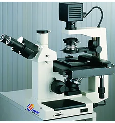
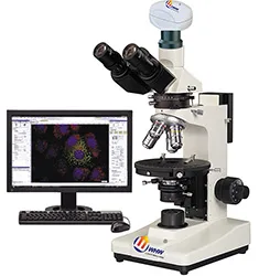
BID-200 Biological Microscope
Biological Microscope
型番BID-200
- 光学放大倍数100X~400X
- 机械筒长160mm
- 物镜共轭距离195mm
- 目镜接口直径23.2mm
By submitting you agree to our privacy policy.
01
製品概要
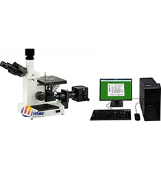
BID-200倒置生物显微镜配置长工作距离平场消色差物镜与大视野目镜与旋转摆入摆出式聚光镜,可拆卸式机械移动载物装置可以满足不同高度培养皿观察的需要。产品结构紧凑,操作部位设计合理,使观察者在操作仪器中感到轻松、舒适。产品适合于对细胞组织,透明液态组织的显微观察,也可以对培养皿中的培养组织进行动态显微观察。可应用于科研所、高等院校、医疗卫生、检验检疫、农牧乳业等部门。
一、性能特点:
1、铰链式双目观察镜筒,单视度可调,镜筒30度倾斜;
2、双层机械移动载物台,配备三种不同规格的培养皿托板,适用于不同培养皿的观察需求;
3、旋转摆入摆出式聚光系统,可对高培养皿或圆筒状烧瓶进行无沾染培养细胞观察;
4、配置高品质相衬平场物镜与相衬聚光镜,拉板式与插板式相衬聚光镜适合不同的操作需求;
5、大视野目镜,视场范围直径20mm;
二、技术参数:
光学放大倍数:100X~400X;
机械筒长:160mm;
物镜共轭距离:195mm;
目镜接口:直径23.2mm;
齐焦距离:10mm;
目镜:大视野WF10X(Φ20mm);
长距平场消色差物镜PLL:10X/0.25\工作距离8.8mm,25X/0.4\4.8mm,40X/0.6\3.3mm;
长距平场消色差相衬物镜PLL:10X/0.25\工作距离8.8mm,PHP2;
目镜筒:三目镜(倾斜30度),100%通光摄影,瞳距53~75mm;
调焦机构:粗微动同轴调焦, 粗动松紧可调,带锁紧和限位装置,微动格值:2μm;
转换器:四孔(滚珠内定位);
载物台:双层机械移动式,尺寸224*208mm,移动范围:130mm*79mm,移动尺可拆卸;
标本架:77.5*34,可适配直径68.5圆形培养皿
标本架:适合放置82mmX57mm培养器皿;
标本架:129.5mmX86mm,适配直径87.5圆形培养皿;
透射照明系统:6V30W卤素灯,亮度可调;
滤色片:蓝滤色片、绿滤色片、磨砂玻璃;
拉板式相衬装置:对中望远镜;
拉板式相衬装置:10X拉板式相衬环板;
拉板式相衬装置:聚光镜升降可调, NA.=0.4,工作距离:50mm;
聚光镜:工作距离55mm,带相衬装置;
三、选配配件:
1、目镜:WF16X(Φ11mm),分划目镜10X(Φ20mm),格值0.1mm/格;
2、转换器:五孔(滚珠内定位);
3、聚光镜:超长工作距离,带滤色片座,工作距离:70mm;
4、样本适配器:
孔座最大直径50.5mm,中心距离63mm,适配外径50mm培养皿观察;
孔座最大35.5mm,适配外径35mm培养皿观察;
孔座最大尺寸51.5X74.5mm,适配T25型培养皿观察;
孔座最大尺寸66.5X66.5mm,适配66X66mm方形培养皿观察;
孔座最大尺寸76.6X26.2mm,适配标准载玻片样品观察;
5、滤色片:黄滤色片;
6、拉板式相衬物镜:长距离平场消色差相衬物镜PLL 25X/0.40 PHP2、PLL 40X/0.60 PHP2;
7、拉板式相衬环板:25X、40X;
8、数码相机接口;
9、USB、VIDEO输出接口;
10、摄影装置;
BID-200 Biological Microscope supplied by CHWES. 17 key specifications available on request.
02
仕様
| 光学放大倍数 | 100X~400X |
|---|---|
| 机械筒长 | 160mm |
| 物镜共轭距离 | 195mm |
| 目镜接口 | 直径23.2mm |
| 齐焦距离 | 10mm |
| 目镜 | 大视野WF10X(Φ20mm) |
| 长距平场消色差物镜PLL | 10X/0.25\工作距离8.8mm,25X/0.4\4.8mm,40X/0.6\3.3mm |
| 长距平场消色差相衬物镜PLL | 10X/0.25\工作距离8.8mm,PHP2 |
| 目镜筒 | 三目镜(倾斜30度),100%通光摄影,瞳距53~75mm |
| 调焦机构 | 粗微动同轴调焦, 粗动松紧可调,带锁紧和限位装置,微动格值:2μm |
| 转换器 | 四孔(滚珠内定位) |
| 载物台 | 双层机械移动式,尺寸224*208mm,移动范围:130mm*79mm,移动尺可拆卸 |
| 标本架 | 77.5*34,可适配直径68.5圆形培养皿 |
| 透射照明系统 | 6V30W卤素灯,亮度可调 |
| 滤色片 | 蓝滤色片、绿滤色片、磨砂玻璃 |
| 拉板式相衬装置 | 对中望远镜 |
| 聚光镜 | 工作距离55mm,带相衬装置 |
* Generated by rule engine over the product database; for pre-selection only.
03
測定原理
The metallurgical microscope uses an infinity-corrected optical path with reflected Köhler illumination. Light passes the collector, field stop and aperture stop, is deflected by a semi-transparent mirror through the objective onto the specimen, and returns through the same objective to the eyepiece or camera.
- Bright field for routine microstructure, inclusions and decarburised layers.
- Dark field collects scattered light to reveal grain boundaries, cracks and non-metallic inclusions.
- Polarised light identifies anisotropic phases, spheroidised structures and coating stress.
- DIC converts tiny height differences into contrast, ideal for polished, unetched samples.
Objectives of 5× to 100× are combined with 10× eyepieces. Higher numerical aperture gives better resolution but shallower depth of field.
04
Process animation
- Sampling and preparation: sectioning, mounting, grinding, polishing, etching.
- Illumination and focus: select BF/DF/POL/DIC and focus.
- Image capture: trinocular port, 1× camera adapter, white balance.
- Scale calibration: calibrate µm per pixel with a stage micrometer.
- Measurement: grain size, case depth, coating thickness, inclusion rating.
05
Calculation & formulas
1. System magnification: M = objective × eyepiece × adapter, e.g. 40× / 10× / 1× = 400×.
2. Resolution: d = 0.61λ/NA (λ≈550 nm). A 40× objective with NA 0.65 resolves 0.52 µm; an NA 0.95 dry objective reaches 0.35 µm.
3. Depth of field scales with λ/NA² — higher NA, shallower depth; use low NA for fracture surfaces.
4. Grain size (GB/T 6394): at 100×, grains N per 645 mm² field follow N = 2G−1; counting 128 grains gives G = log2128 + 1 = 8. Intercept method: mean intercept L̄ = line length ÷ intercepts, G = −6.6437 lg L̄ (mm, 100×).
5. Effective case depth: distance to 550 HV1, fitted from a micro-hardness traverse and averaged over three positions.
06
規格
| Standard | Title | Scope |
|---|---|---|
| GB/T 13298-2015 | Metallic materials — examination of microstructure | Microstructure rating |
| GB/T 6394-2017 | Determination of average grain size | Grain size |
| ASTM E3-11 | Guide for metallographic specimen preparation | Preparation |
| ASTM E112 | Determining average grain size | Grain size |
| ISO 643 | Steels — micrographic determination of grain size | Grain size |
Export projects often require dual GB and ASTM reports; the software ships both rating charts.
07
選定ガイド
1. Surface or cross-section: stereo microscopes (HX-ZG7, XSZ) for fracture surfaces, solder joints and coatings; upright or inverted metallurgical microscopes (HX-4, HX-G series) for microstructure, case depth and inclusions.
2. Upright or inverted: upright for small specimens that are flipped often; inverted (HX-G3A/G4C/G5A) for large, heavy parts such as gears, shafts and tube sections that go straight onto the stage without re-mounting.
3. Optics set the ceiling: plan achromats cover routine rating; semi-apochromats or apochromats with a research stand (HX-G5A) are needed for 1000× precipitates and brightfield/darkfield/polarised switching.
4. Three levels of digitalisation: a 5 MP camera for images; camera plus analysis software (grain size, case depth, inclusions, porosity) for automatic rating and reports; motorised stage with scanning and stitching for unattended batches.
5. Do not forget accessories: polariser, darkfield, DIC, and a microhardness interface.
6. Room: an anti-vibration bench at 20±3 °C for research stands; keep preparation and microscopy rooms separate to avoid abrasive dust.
| Series | Type | Typical task | Recommended setup |
|---|---|---|---|
| HX-4A / HX-4B | Upright metallurgical | Routine structure, case depth | 5×/10×/40× + 5 MP camera |
| HX-G2A / G2B | Inverted | Batch samples, no re-mounting | Brightfield + simple polariser |
| HX-G3A | Trinocular inverted | Case depth, rating, reports | Camera + analysis software |
| HX-G4C / G5A | Research inverted | Darkfield/polarised/DIC | Semi-apochromat + motorised stage |
| HX-ZG7 / XSZ-146 | Stereo | Fracture, solder, low-mag locating | Zoom + ring light |
Common misconceptions: higher magnification is not better (numerical aperture limits resolution, 100× dry is the practical ceiling); ignoring stage travel so large samples do not fit; buying the stand without software and still rating by eye, which kills repeatability.
08
試験方法
Preparation. Section perpendicular to the feature of interest. Keep hot-mounting below 150 °C for aluminium and quenched parts, or use cold mounting. Grind 320→600→800→1200, removing previous scratches at each step; polish with 3 µm then 1 µm diamond. Etchants: 4% nital for carbon steel (3–8 s), aqua regia or electrolytic for stainless, Keller for aluminium.
Examination. Locate a representative field at 5×/10×, then switch to higher power. Rate grain size to GB/T 6394 by comparison or intercept. Measure case depth at 500× with an ocular scale or calibrated software, averaging five readings.
Calibration. Verify µm/pixel daily with a stage micrometer, check against a certified specimen quarterly, record three fields per sample and archive images with scale bars.
Pitfalls. Over-etching widens boundaries and fakes decarburisation; residual scratches can be mistaken for cracks; rounded mounting edges inflate case depth. Keep an unetched specimen for coating and crack review.
09
Industry applications
- Steel and heat treatment: decarburised depth, carburised/nitrided case depth, grain size (GB/T 6394), non-metallic inclusions (GB/T 10561), banding and Widmanstätten rating.
- Non-ferrous metals: aluminium grain and recrystallisation, alpha/beta ratio in brass, twinning and corrosion morphology in magnesium.
- Welding and brazing: penetration, HAZ width, porosity and cracks, intermetallic thickness at dissimilar joints.
- Additive manufacturing: porosity, lack-of-fusion defects, melt-pool morphology in SLM parts, porosity repeatability within 0.2%.
- Bearings and gears: martensite rating, retained austenite, carbide network and banding, grinding burn and white layer.
- Electronics: IMC thickness, plating cross-sections, PCB micro-sections, gold wire ball bonds (stereo plus metallurgical).
- Powders and ceramics: particle morphology and size, sintered porosity, coating cross-section thickness.
- Failure analysis: fracture surface macro and micro morphology, corrosion products, crack path and origin, with stereo microscopy for low-magnification locating.
10
Price and lead time for this model
同シリーズ
すべて見る→Microscopes
HOT HOT
 HOT